Stirring production line

A production line and mixing device technology, which is applied to cement mixing devices, batching weighing instruments, and raw material supply devices for sale, etc., can solve the problems of reducing processing efficiency, time-consuming and laborious, and low efficiency, so as to reduce equipment costs and avoid easy knots. The scab, the effect of the simple structure of the device

Inactive Publication Date: 2018-03-16
谭自创
View PDF6 Cites 1 Cited by
  • Summary
  • Abstract
  • Description
  • Claims
  • Application Information

AI Technical Summary

Problems solved by technology

Generally, the mixer is equipped with an aggregate bin and a powder bin, as well as a stirring device connected to these two bins. The aggregate and powder enter the stirring device from their respective bins and are mixed evenly through the stirring device. However, in the actual operation process , due to the high humidity in the mixing bin, the outlet of the powder bin is prone to scabbing, which will affect the subsequent entry of the powder into the mixing bin. At this time, the operator needs to stop to clean the scab at the outlet of the powder bin, which is time-consuming It is laborious; and the existing mixer generally adopts the method of manual feeding, and the aggregate or sub-material is directly added to the aggregate bin and the powder bin. Since the aggregate and powder need to be mixed in a certain proportion, it is necessary to Weighing greatly reduces the processing efficiency; and after the mixing is completed, the materials are generally transported out manually, which is less efficient and consumes a lot of manpower

Method used


Image

  • Stirring production line

Examples


Example Embodiment

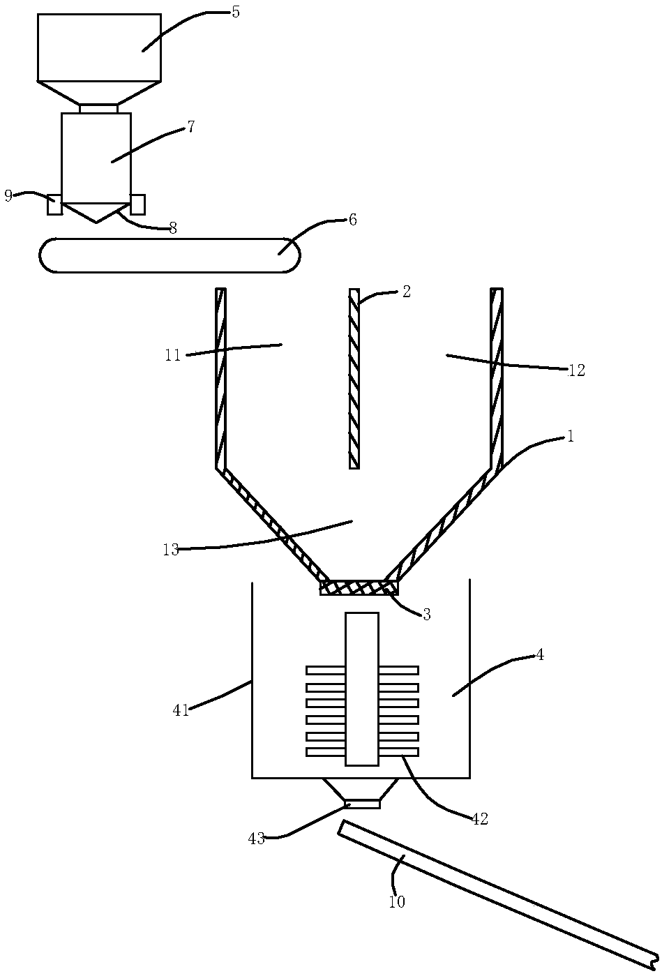
[0016] refer to figure 1 , A stirring production line of the present invention includes a feed bin 1, the upper part of the feed bin 1 is longitudinally provided with a separator 2, and the separator 2 divides the feed bin 1 into an aggregate bin 11 and a powder bin 11. The silo 12, the lower part of the feeding silo 1 is provided with a mixing cavity 13, the mixing cavity 13 is connected with the aggregate silo 11 and the powder silo 12, and a stirring device 4 is arranged below the mixing cavity 13 . When in use, lime and other powders enter from the powder silo 12, and aggregates such as stone particles enter from the aggregate silo 11. After being mixed in the mixing chamber 13, they are discharged from the outlet of the mixing chamber 13. Since the stirring device 4 is relatively wet, Therefore, the powder is easy to scab, but the setting of the separator 2 and the mixing chamber 13, even if the powder is partially scabbed due to moisture, it will be hit by the aggregates s


PUM


Abstract

The invention discloses a stirring production line. The stirring production line comprises a feeding bin. The upper part of the feeding bin forms an aggregate bin and a powder bin by a partition plate. The lower part of the feeding bin is provided with a mixing cavity communicating with the aggregate bin and the powder bin. Two existing separating cavities are merged into one, so that the equipment cost is reduced. In a discharging outlet of the mixing cavity, even if partial scabbing happens because of dampness, scab can further be crushed by collision of aggregate such as stone and steel discharged from the aggregate bin, so that scab is broken, the phenomenon that an outlet of a powder bin is prone to scabbing in the prior art is effectively avoided, and the time cost and the manpower cost of manual maintenance are omitted. The whole device structure is simple, other devices do not need to be arranged additionally, the cost is low, and practicability is high; the stirring productionline is further provided with a first feeding device and a second feeding device, automatic weighing of materials can be achieved, and the machining efficiency is improved greatly; and a stirring device is connected with a material conveying device through a discharging door, automatic discharging of the materials can be achieved, and the machining efficiency is further improved.

Description


Claims


Application Information

Patent Timeline
Owner 谭自创
Why Eureka
Try Eureka