Liquid fuel combustion device and combustion system

A liquid fuel and combustion device technology, which is applied to the combustion of liquid fuel and gaseous fuel, the combustion of multiple fuels, the combustion of block fuel and gaseous fuel, etc., and can solve the problem of large liquid fuel particles and small specific surface area, etc. problem, to achieve the effect of improving the utilization rate

Pending Publication Date: 2018-05-04
蔡悦胜
View PDF0 Cites 0 Cited by
  • Summary
  • Abstract
  • Description
  • Claims
  • Application Information

AI Technical Summary

Benefits of technology

This new type of engine has two main technical features that make it more efficient than traditional engines by allowing for complete burning of liquids without leaving behind any residue or waste products after they have been used up over time.

Problems solved by technology

The technical problem addressed in this patented method relates how efficiently use liquid fuels without causing them to become larger or smaller than what they should have before burning out (the size of these tiny droplets).

Method used


Image

  • Liquid fuel combustion device and combustion system
  • Liquid fuel combustion device and combustion system
  • Liquid fuel combustion device and combustion system

Examples


Embodiment 1

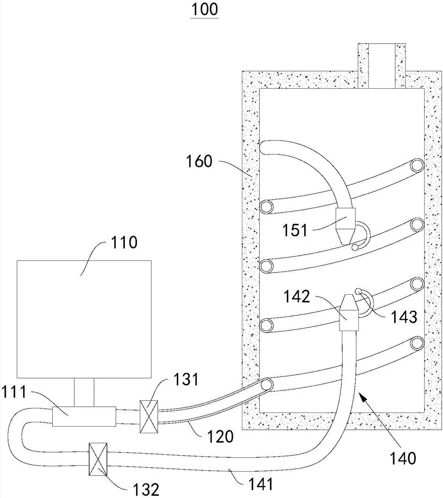
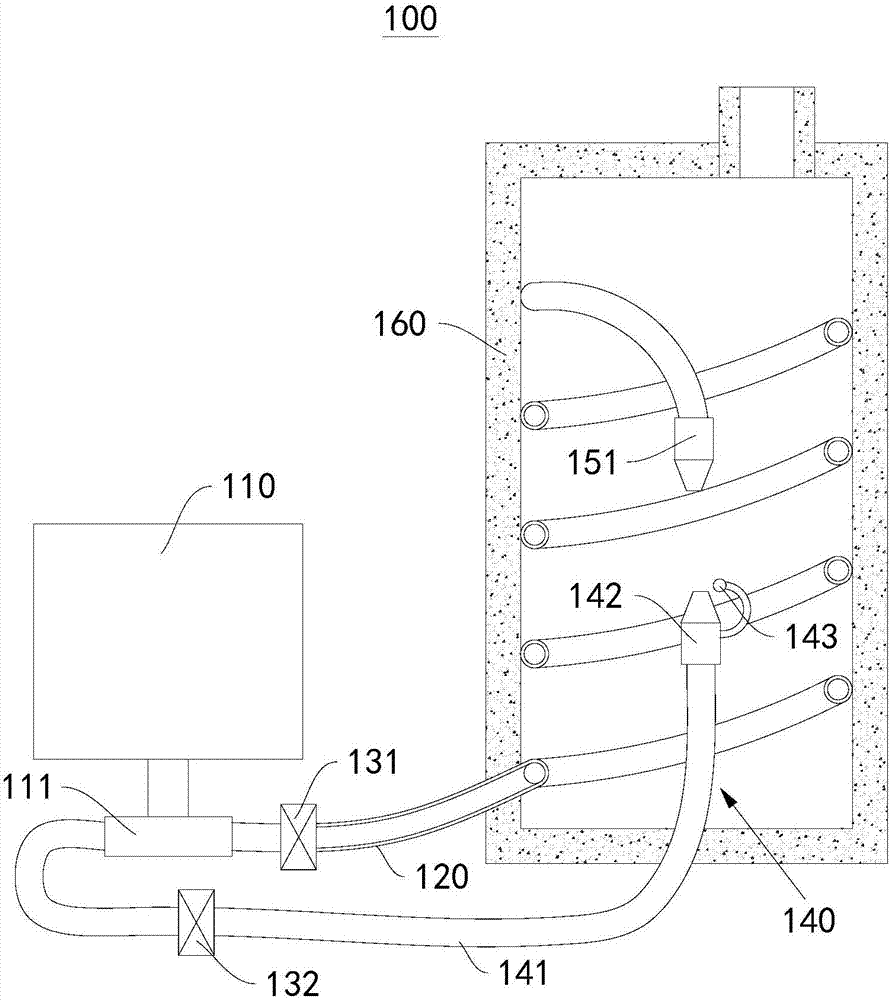
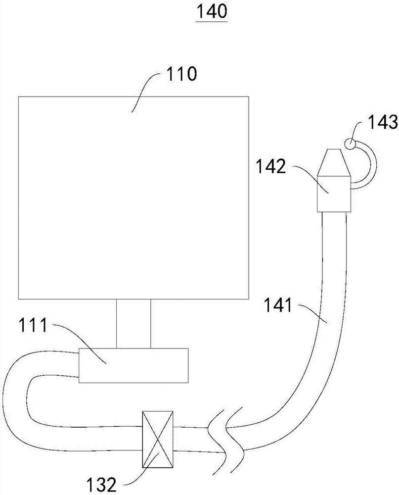
[0036] This embodiment provides a liquid fuel combustion device 100, please refer to figure 1 , figure 2 , image 3 as well as Figure 4 , this liquid fuel combustion device 100 includes:

[0037] combustion chamber 160;

[0038] The first pipeline 120, the first pipeline 120 is at least partly located inside the combustion chamber 160, and the first nozzle 151 is connected to one end of the first pipeline 120 located inside the combustion chamber 160;

[0039] A heating mechanism 140, the heating mechanism 140 is connected to the combustion chamber 160, and the heating mechanism 140 is used to heat the combustion chamber 160;

[0040] The fuel supply mechanism 110 , the fuel supply mechanism 110 communicates with the first pipeline 120 , and the fuel supply mechanism 110 is used to deliver liquid fuel to the first pipeline 120 .

[0041] In the inside of the combustion chamber 160, at first realize the heating to the combustion chamber 160 by the heating mechanism 140, bec

Embodiment 2

[0071] This embodiment provides a combustion system, which includes the liquid fuel combustion device 100 provided in Embodiment 1.

[0072] Optionally, this combustion system also includes a solid fuel combustion device for burning solid fuel and a gaseous fuel combustion device for burning gaseous fuel, wherein the liquid fuel combustion device 100 is the liquid fuel combustion device 100 provided in Embodiment 1.

[0073] The working principle of the combustion system provided in this embodiment is that, during operation, the liquid fuel combustion device 100 can be used to achieve full combustion of liquid fuel, improve the utilization rate of liquid fuel, and thus improve the utilization of fuel in the entire combustion system Rate.


PUM


Abstract

The invention provides a liquid fuel combustion device and a combustion system and belongs to the field of combustion devices. The liquid fuel combustion device comprises a combustion chamber, a firstpipeline, a heating mechanism and a fuel supply mechanism, wherein at least part of the first pipeline is located in the combustion chamber; a first nozzle is connected to the end, located in the combustion chamber, of the first pipeline; the heating mechanism is connected with the combustion chamber and used for heating the combustion chamber; the fuel supply mechanism communicates with the first pipeline and is used for supplying liquid fuel to the first pipeline. The combustion system comprises the liquid fuel combustion device. Through the liquid fuel combustion device and the combustionsystem, liquid fuel going into the combustion chamber can be converted from a liquid phase into a gas phase so that the liquid fuel can be combusted fully, and the utilization rate of the liquid fuelcan be increased.

Description


Claims


Application Information

Patent Timeline
Owner 蔡悦胜
Why Eureka
Try Eureka