Carbon fiber composite material enhanced ultrahigh pressure movable bend

A technology of composite materials and swivel elbows, applied in the direction of elbows, pipes/pipe joints/fittings, siphons, etc., can solve the problems of short service life of elbows, inconvenient installation and transportation, and bulky elbows, etc., to achieve Improve the safety of use, good operability, increase the effect of flexibility

Inactive Publication Date: 2018-05-18
中石化四机石油机械有限公司 +1
View PDF8 Cites 3 Cited by
  • Summary
  • Abstract
  • Description
  • Claims
  • Application Information

AI Technical Summary

Benefits of technology

This patented technology allows for better performance when used on an arm or leg prosthetic device due to its improved design features such as high torque resistance, easy rotation without damaging it's components, durability against corrosion caused by fluids like water, and enhanced security measures. Additionally, this technology makes it easier to install and maintain these devices because there may also be parts inside them protected from damage.

Problems solved by technology

This patented technical problem addressed in this patents relates to improving the durability and lifespan of conventional hydrocrackers' internal joints that use specialized tools like drill bits or pipelining equipment during maintenance work on these facilities. These traditional methods involve exposing them to highly abrasive environments caused by fluids from the process itself. Additionally, they may be dangerous when exposed overheated causing cracks at their edges. To address these issues, researchers developed different types of plastic composites made up mostly of sintered ceramics instead of metal alloys.

Method used


Image

  • Carbon fiber composite material enhanced ultrahigh pressure movable bend
  • Carbon fiber composite material enhanced ultrahigh pressure movable bend
  • Carbon fiber composite material enhanced ultrahigh pressure movable bend

Examples


Embodiment Construction

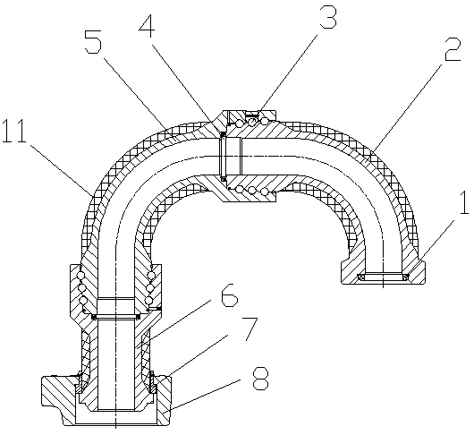
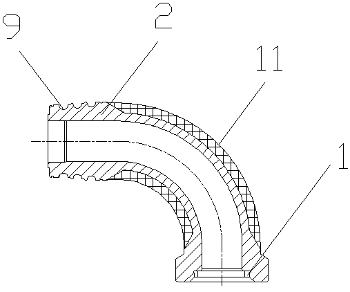
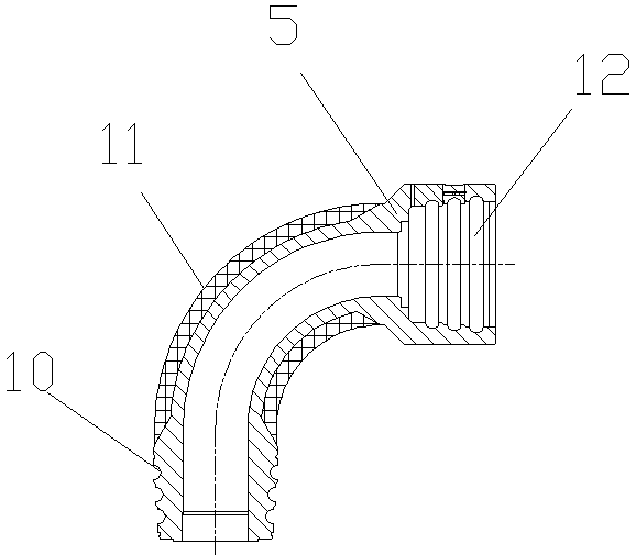
[0022] The technical solutions of the present invention will be further clearly and completely described below in conjunction with the accompanying drawings.

[0023] See attached Figure 1-4

[0024] 1. Elbow processing: First, AD elbow 2, AB elbow 5 and BC straight head 6 are processed and formed according to the basic shape of the metal, including the union joints at both ends of each elbow, AD elbow 2, and AB elbow 5 The upper steel ball groove 9 and the lower steel ball groove 10, the inner ball track 12 of the AB elbow 5 and the BC straight head 6, and the stopper at the end of the BC straight head 6. Then, according to the set process, the carbon fiber composite material 11 is respectively inlaid on the outer surface of the AD elbow 2, the AB elbow 5 and the BC straight end 6. The number of coating layers and the process need to be specially designed. To determine the required reinforcement effect and product structure, the outer layer of the carbon fiber composite mater


PUM


Abstract

The invention provides a carbon fiber composite material enhanced ultrahigh pressure movable bend. The movable bend is provided with a seal ring on the end portion of an AD bend; the AD bend is connected to an AB bend; steel balls are mounted in an upper steel ball slot and an inner ball channel at the connection; a packing is mounted at the connection of the AD bend and the AB bend; a retainer ring and a wing-shaped nut are mounted on the end portion of a BC straight head; the BC straight head is connected to the AB bend; steel balls are mounted in a lower steel ball slot 10 and an inner ballchannel at the connection; and carbon fiber composite materials externally cover the AD bend, the AB bend and the BC straight head. As the carbon fiber composite materials externally cover the AD bend, the AB bend and the BC straight head and have ultrahigh tensile strength, the strength of the bend and the straight head is improved effectively. The movable bend can bear 140MPa and over ultrahighpressure fluid.

Description


Claims


Application Information

Patent Timeline
Owner 中石化四机石油机械有限公司
Why Eureka
Try Eureka