Full-automatic dye mixing device for printing and dyeing mill
A mixing device and fully automatic technology, which is applied to mixers with rotating stirring devices, mixers, transportation and packaging, etc., can solve the problems of reduced activity of dyes, low color fastness of cloth, and affecting the quality of cloth, so as to improve the activity , Low input cost, easy to promote the effect
- Summary
- Abstract
- Description
- Claims
- Application Information
AI Technical Summary
Benefits of technology
Problems solved by technology
Method used
Image

Examples
Embodiment 1
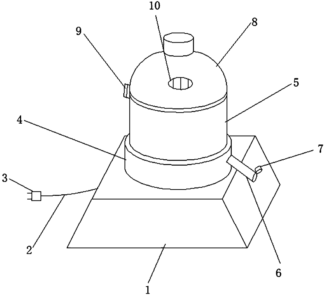
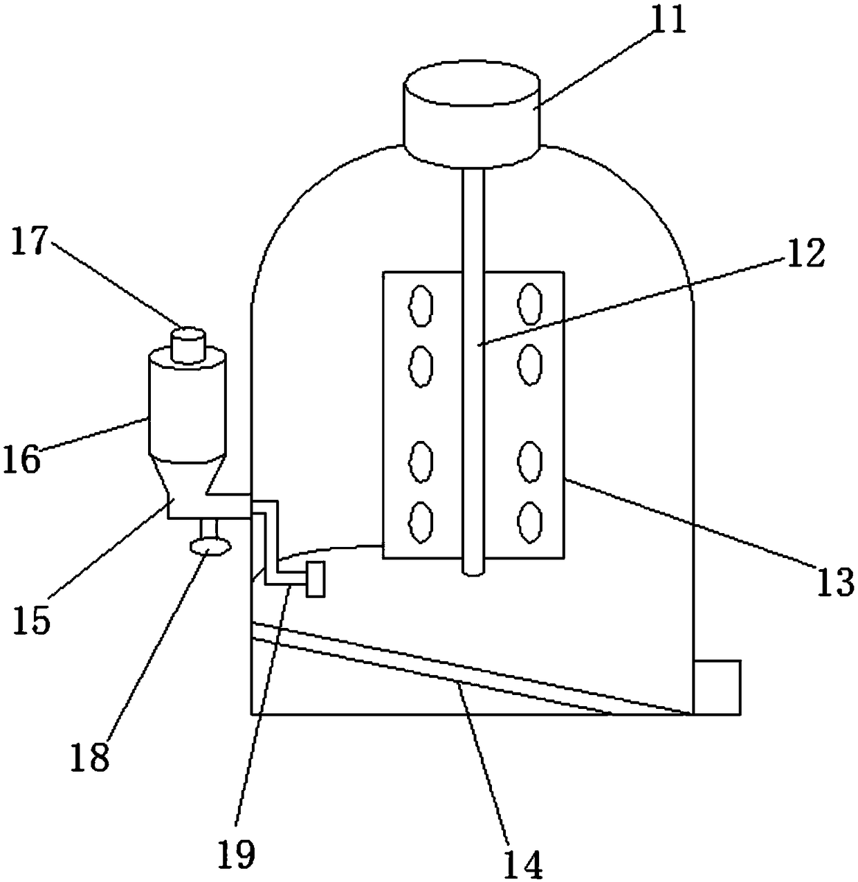
[0026] see Figure 1-2 , a fully automatic dye mixing device used in printing and dyeing factories in the present invention, comprising a base 1, a heatable sleeve 4 is fixed on the upper part of the base 1, and a mixing bucket 5 is fixed on the top of the heatable sleeve 4, so One side of the mixing bucket 5 is provided with a dye outlet pipe 6, the top of the dye outlet pipe 6 is provided with a sealing plug 7, the top of the mixing bucket 5 is provided with a hemispherical lid 8, and the hemispherical The bung 8 is hinged with the mixing bucket 5 by connecting the hinges 9, the top of the hemispherical bung 8 is provided with a heat dissipation port 10, and the top of the hemispherical bung 8 is fixed with a drive motor 11, and the drive motor 11 is connected with the transmission shaft 12, and drives the transmission shaft 12 to rotate. The transmission shaft 12 is provided with a stirring blade 13, and the bottom of the mixing bucket 5 is provided with a deflector 14. One si
Embodiment 2
[0028] see Figure 1-2 , a fully automatic dye mixing device used in printing and dyeing factories in the present invention, comprising a base 1, a heatable sleeve 4 is fixed on the upper part of the base 1, and a mixing bucket 5 is fixed on the top of the heatable sleeve 4, so One side of the mixing bucket 5 is provided with a dye outlet pipe 6, the top of the dye outlet pipe 6 is provided with a sealing plug 7, the top of the mixing bucket 5 is provided with a hemispherical lid 8, and the hemispherical The bung 8 is hinged with the mixing bucket 5 by connecting the hinges 9, the top of the hemispherical bung 8 is provided with a heat dissipation port 10, and the top of the hemispherical bung 8 is fixed with a drive motor 11, and the drive motor 11 is connected with the transmission shaft 12, and drives the transmission shaft 12 to rotate. The transmission shaft 12 is provided with a stirring blade 13, and the bottom of the mixing bucket 5 is provided with a deflector 14. One si
Embodiment 3
[0030] see Figure 1-2, a fully automatic dye mixing device used in printing and dyeing factories in the present invention, comprising a base 1, a heatable sleeve 4 is fixed on the upper part of the base 1, and a mixing bucket 5 is fixed on the top of the heatable sleeve 4, so One side of the mixing bucket 5 is provided with a dye outlet pipe 6, the top of the dye outlet pipe 6 is provided with a sealing plug 7, the top of the mixing bucket 5 is provided with a hemispherical lid 8, and the hemispherical The bung 8 is hinged with the mixing bucket 5 by connecting the hinges 9, the top of the hemispherical bung 8 is provided with a heat dissipation port 10, and the top of the hemispherical bung 8 is fixed with a drive motor 11, and the drive motor 11 is connected with the transmission shaft 12, and drives the transmission shaft 12 to rotate. The transmission shaft 12 is provided with a stirring blade 13, and the bottom of the mixing bucket 5 is provided with a deflector 14. One sid
PUM
 Abstract
Description
Claims
Application Information
 - R&D Engineer
- R&D Manager
- IP Professional
- Industry Leading Data Capabilities
- Powerful AI technology
- Patent DNA Extraction
Browse by: Latest US Patents, China's latest patents, Technical Efficacy Thesaurus, Application Domain, Technology Topic.
© 2024 PatSnap. All rights reserved.Legal|Privacy policy|Modern Slavery Act Transparency Statement|Sitemap