electrical connector

A technology of electrical connectors and welding parts, which is applied in the direction of connection, two-part connection device, and parts of the connection device. It can solve the problems of lack of aesthetics, poor blocking and positioning effect, etc., to prevent backlash and facilitate manufacturing. Effect

Active Publication Date: 2020-01-24
FOXCONN (KUNSHAN) COMPUTER CONNECTOR CO LTD +1
View PDF1 Cites 0 Cited by
  • Summary
  • Abstract
  • Description
  • Claims
  • Application Information

AI Technical Summary

Benefits of technology

The technical effects are that this new design allows an electric connection between two parts without requiring any extra components like another part or adding other structures around it. This makes assembly easier while maintains its strength.

Problems solved by technology

This patented technical problem addressed by this patents relates to improving the appearance of conventional connectors used with electronic devices such as smartphones due to their lack of effective lockings during use.

Method used


Image

  • electrical connector
  • electrical connector
  • electrical connector

Examples


Embodiment Construction

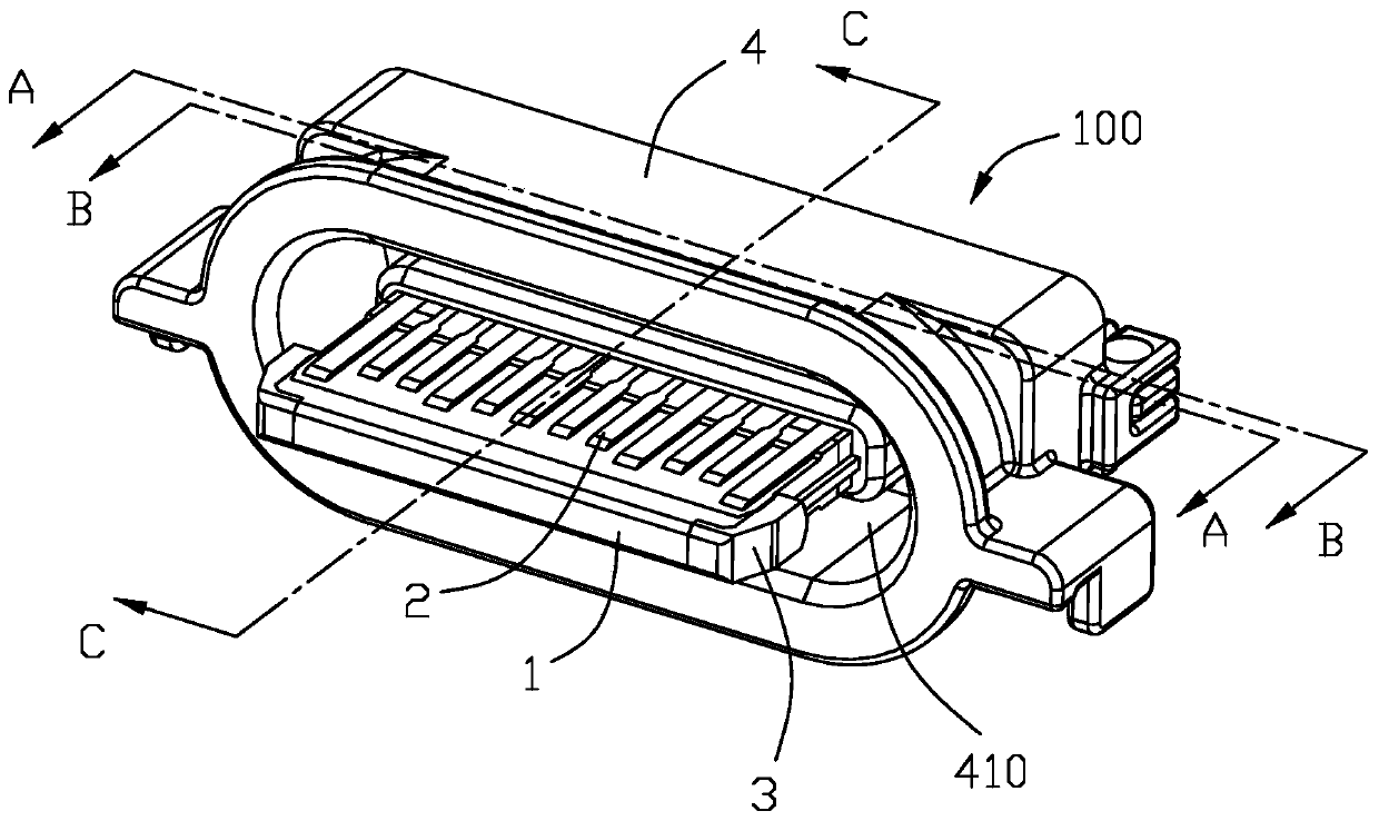
[0054] Below, will combine Figure 1 to Figure 12 The first embodiment of the electrical connector 100 of the present invention is introduced. The port where the electrical connector 100 is plugged with the plug connector is defined as a plugging end. Define a docking direction, a transverse direction, and a vertical direction perpendicular to both the docking direction and the transverse direction, and the plane where the docking direction and the transverse direction are located constitutes a horizontal plane.

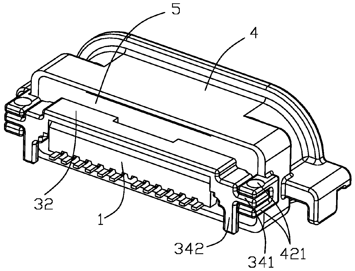
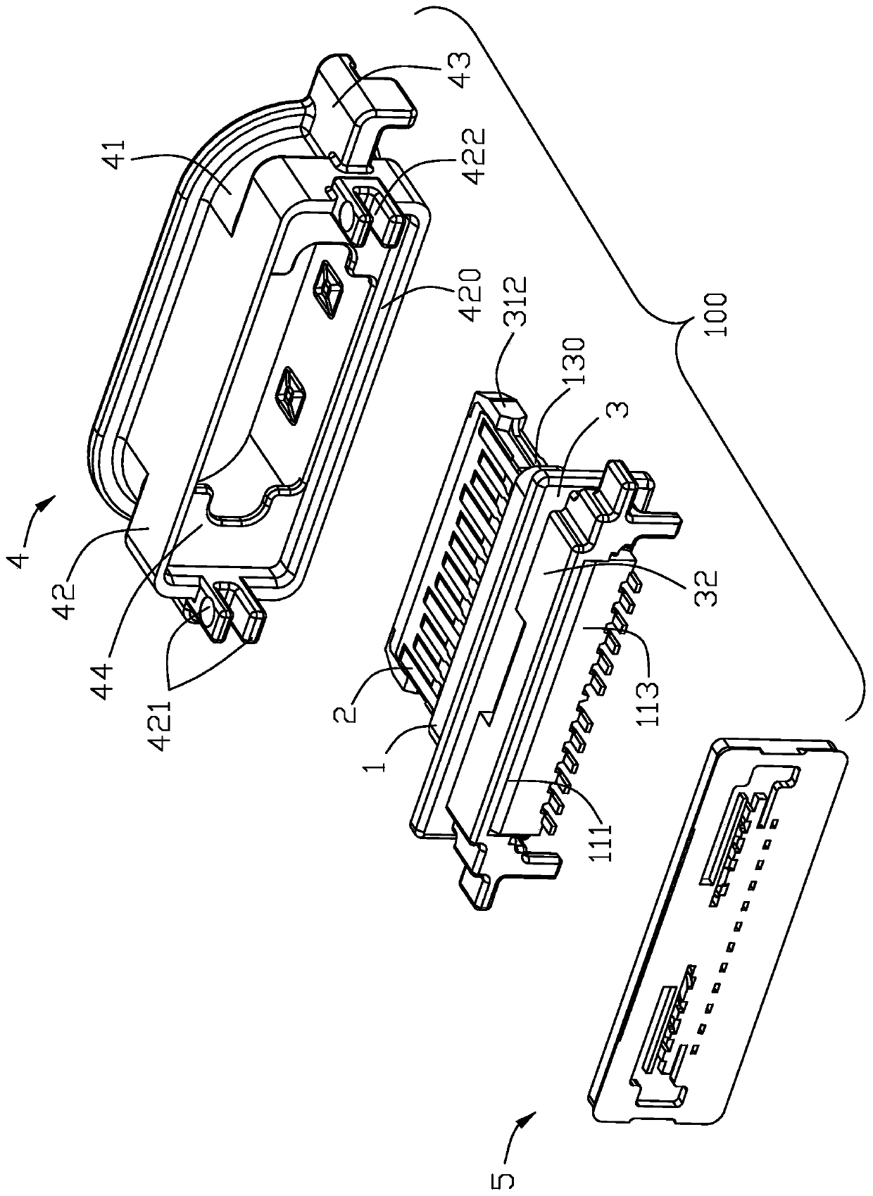
[0055] Please refer to Figure 1 to Figure 12 As shown, the electrical connector 100 of the present invention includes an insulating body 1, a conductive terminal 2 held in the insulating body 1, a metal reinforcement 3, a shielding shell 4 wrapped outside the insulating body 1, and a molded at the rear end of the insulating body 1. glue wall5.

[0056] Please refer to Figure 4 to Figure 9 As shown, the insulating body 1 includes an upper insulating part 11 , a low


PUM


Abstract

An electrical connector includes: a metallic frame having a main part, a board at a rear of the main part, and an upper shield behind the board; an upper and lower contact modules arranged at two opposite sides of the metallic frame main part, each contact module having a row of contacts, each contact having a contacting portion, an intermediate portion, and a tail; an insulative housing having a base and a tongue; a shielding shell accommodating the board of the metallic frame and enclosing the insulative housing, the contact tails of at least one of the upper and lower contact modules extending rearward beyond a rear end of the shielding shell; wherein the upper shield of the metallic frame shields the contact tails of the at least one contact module.

Description


Claims


Application Information

Patent Timeline
Owner FOXCONN (KUNSHAN) COMPUTER CONNECTOR CO LTD
Why Eureka
Try Eureka