Display panel and display device

A display panel and display device technology, applied in the direction of semiconductor devices, electrical components, circuits, etc., can solve the problems of high screen-to-body ratio, lower display quality, disadvantages, etc., achieve high screen-to-body ratio, improve display quality, and increase area Effect

Active Publication Date: 2018-08-17
SHANGHAI TIANMA MICRO ELECTRONICS CO LTD
View PDF4 Cites 15 Cited by
  • Summary
  • Abstract
  • Description
  • Claims
  • Application Information

AI Technical Summary

Problems solved by technology

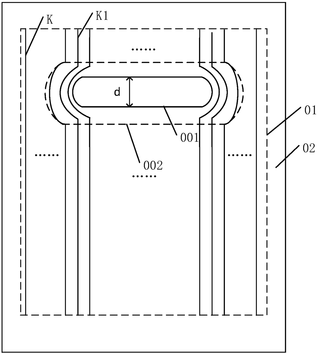
[0004] Since there are a plurality of data lines K in the display area 01, some data lines K1 need to bypass the hollow area 001 at the corresponding position of the hollow area 001, so a winding area 00

Method used


Image

  • Display panel and display device
  • Display panel and display device
  • Display panel and display device

Examples


Embodiment Construction

[0024] Various exemplary embodiments of the present invention will now be described in detail with reference to the accompanying drawings. It should be noted that the relative arrangements of components and steps, numerical expressions and numerical values ​​set forth in these embodiments do not limit the scope of the present invention unless specifically stated otherwise.

[0025] The following description of at least one exemplary embodiment is merely illustrative in nature and in no way taken as any limitation of the invention, its application or uses.

[0026] Techniques, methods and devices known to those of ordinary skill in the relevant art may not be discussed in detail, but where appropriate, such techniques, methods and devices should be considered part of the description.

[0027] In all examples shown and discussed herein, any specific values ​​should be construed as exemplary only, and not as limitations. Therefore, other instances of the exemplary embodiment may ha


PUM


Abstract

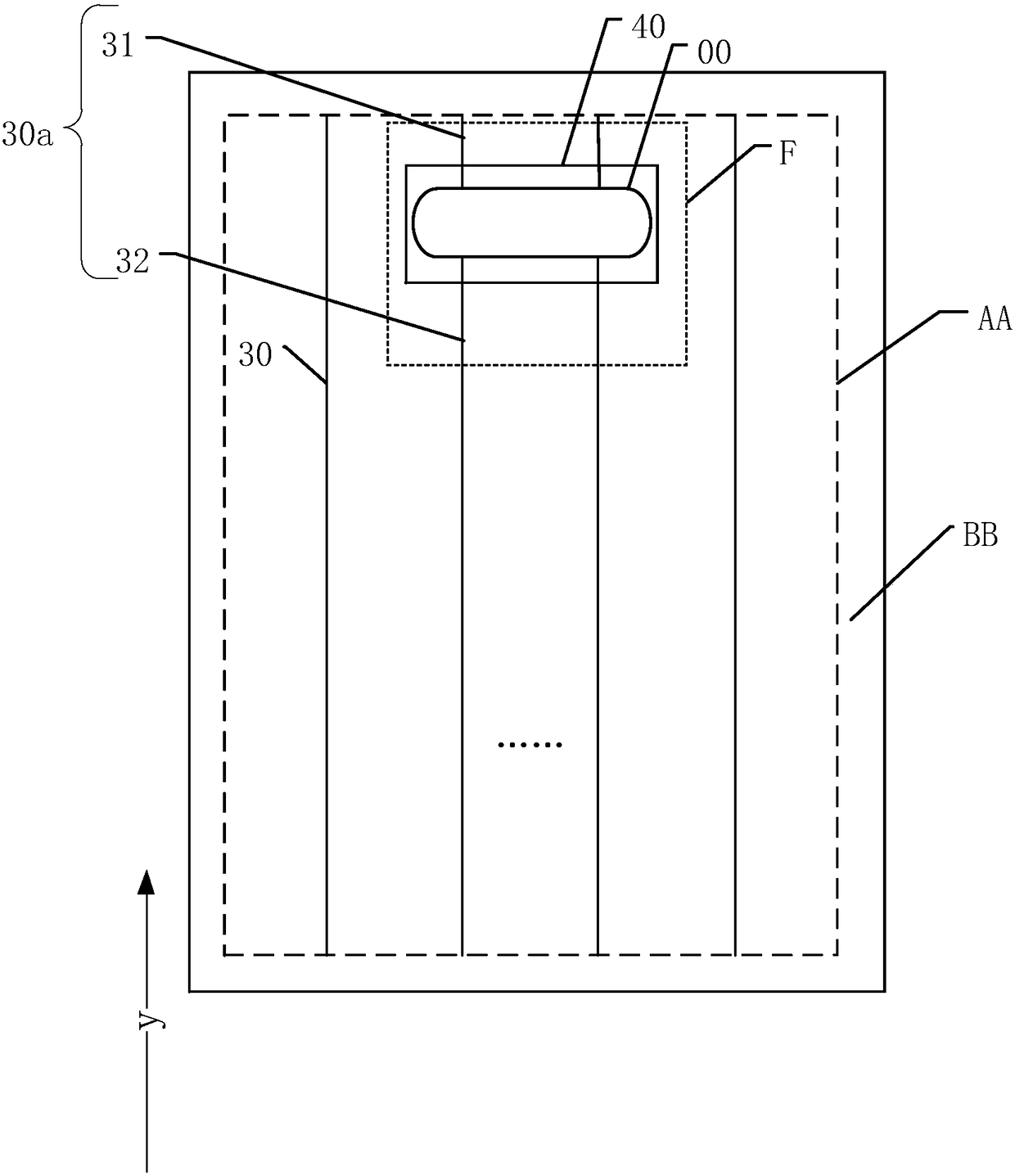
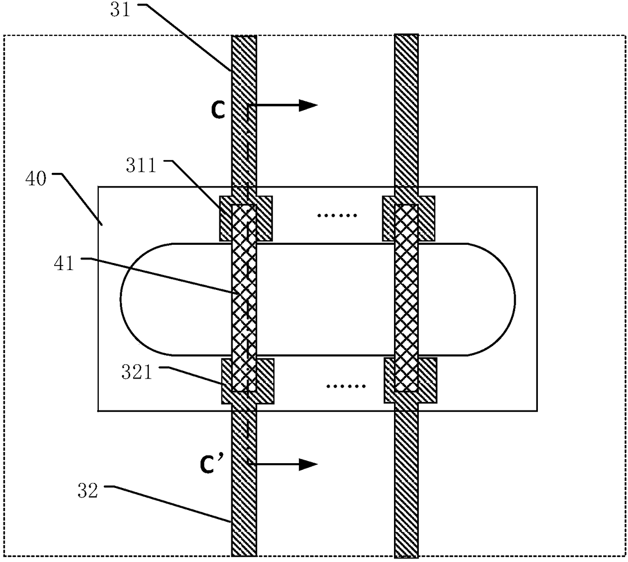
The invention discloses a display panel and a display device, and belongs to the technical field of display. The display panel comprises a display region and a non-display region, the display panel comprises a flexible substrate and a display functional layer, the display panel comprises a hollow part, the display region comprises a plurality of signal lines extending along a first direction, thehollow part penetrates through a film layer where the signal lines are located, each signal line comprises at least one first signal line, the first signal line is partitioned to a first wiring part and a second wiring part by the hollow part, the first wiring part and the second wiring part are electrically connected by a connection wire in a connection substrate, one end of the connection wire is electrically connected with the first wiring part, and the other end of the connection wire is electrically connected with the second wiring part. In the display panel, the connection substrate comprises the connection wire, and the first wiring part, the connection wire and the second wiring part can form a path. Compared with the prior art, the first signal line is not needed to be wound around the hollow part, a winding region cannot be formed, thus, the area of the display region can be expanded, and relatively high screen-to-body ratio is favorably achieved.

Description


Claims


Application Information

Patent Timeline
Owner SHANGHAI TIANMA MICRO ELECTRONICS CO LTD
Why Eureka
Try Eureka