Electric engineering automatic welding machine

An automatic welding machine and electrical engineering technology, applied in welding equipment, laser welding equipment, manufacturing tools, etc., can solve the problems of low welding precision, low intelligence, and lack of positioning function, so as to improve efficiency and intelligence High, highly mechanized effect

Inactive Publication Date: 2018-08-21
郑德辉
View PDF7 Cites 4 Cited by
  • Summary
  • Abstract
  • Description
  • Claims
  • Application Information

AI Technical Summary

Benefits of technology

This patented technology improves upon existing electric arc-welders that use an electronic control system for controlling their operation. It allows them to automatically move along rails without stopping or slow down when they want to be worked on at different locations within a workpiece's surface area. By accurately locating these positions, this technology can improve both precision and speed during automated weldings. Additionally, it enables users to easily change how much pressure needs to apply while performing certain types of operations such as spot welds. Overall, this innovation enhances the performance and functionality of electric arc welders.

Problems solved by technology

This patented describes an electrician's equipment that uses hydraulic power for automated weldings in various industries such as manufacturing or construction environments. However, current methods often result in poor quality welds due to factors like insufficient pressure from gravity during operation (when there may be any movement). Additionally, existing systems require manual labor-intensive steps which can lead to errors when repositioning components after use.

Method used


Image

  • Electric engineering automatic welding machine

Examples


Embodiment Construction

[0013] The following will clearly and completely describe the technical solutions in the embodiments of the present invention with reference to the accompanying drawings in the embodiments of the present invention. Obviously, the described embodiments are only some, not all, embodiments of the present invention. Based on the embodiments of the present invention, all other embodiments obtained by persons of ordinary skill in the art without making creative efforts belong to the protection scope of the present invention.

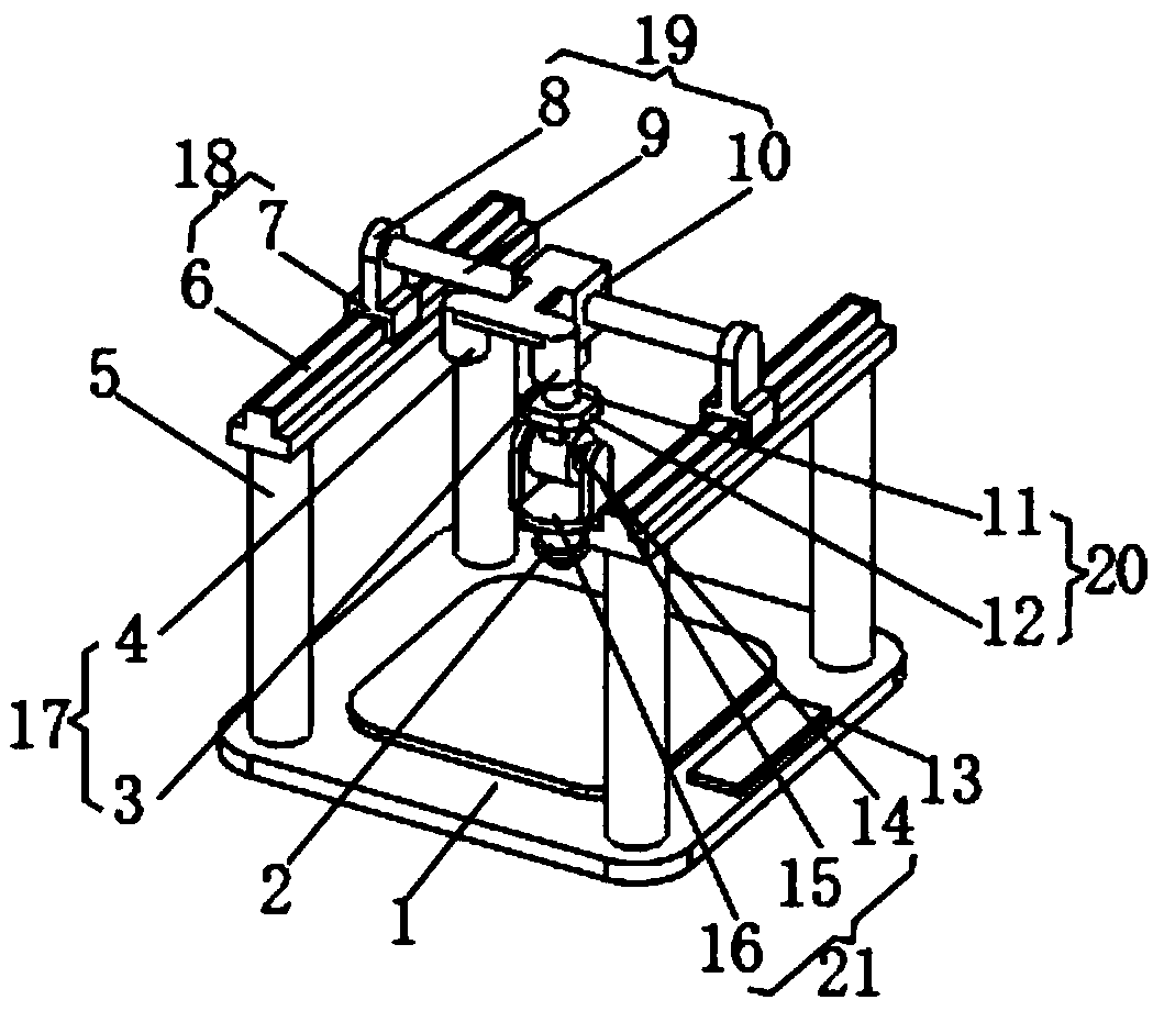
[0014] see figure 1 , the present invention provides a technical solution: an automatic welding machine for electrical engineering, comprising a welding platform 1, an open-source single-chip microcomputer 13 is installed on the top of the welding platform 1, a support rod 5 is fixed on the top of the welding platform 1, and the end of the support rod 5 Connected with horizontal adjustment mechanism 18, vertical adjustment mechanism 19 is installed on the horizon


PUM


Abstract

The invention discloses an electric engineering automatic welding machine. The electric engineering automatic welding machine comprises a welding platform, wherein an open-source singlechip is mountedon the top of the welding platform; a supporting rod is fixed on the top of the welding platform; an end of the supporting rod is connected with a transverse adjusting mechanism; and a longitudinal adjusting mechanism is mounted on the transverse adjusting mechanism. According to the electric engineering automatic welding machine, the working position of the laser welding head is positioned through a positioning device, the intelligence degree is high, positioning is accurate, the welding precision is greatly improved, the transverse working position of the laser welding head is adjusted through the transverse adjusting mechanism, the longitudinal working position of the laser welding head is adjusted through the longitudinal adjusting mechanism, the working height of the laser welding head is adjusted through a lifting mechanism, the working angle of the laser welding head is adjusted through an angle adjusting device, the electric engineering automatic welding machine is good in flexibility and high in degree of mechanization, and the welding efficiency is greatly improved.

Description


Claims


Application Information

Patent Timeline
Owner 郑德辉
Why Eureka
Try Eureka