Mine cable laying device

A cable laying and mining technology, applied in the direction of cable laying equipment, etc., can solve the problems of unfavorable and fast installation, low safety factor, high labor intensity, etc., and achieve the effect of convenient operation, low cost, and reduced labor intensity of personnel

Pending Publication Date: 2018-09-28
ANHUI UNIV OF SCI & TECH
View PDF6 Cites 2 Cited by
  • Summary
  • Abstract
  • Description
  • Claims
  • Application Information

AI Technical Summary

Problems solved by technology

[0002] The driving of equipment in fully mechanized coal mining face is inseparable from power supply, and the laying of cables in the power supply system is a very important link. When using traditional manual laying of cables, it not only needs a lot of labor, labor intensity is high, time-consuming and laborious, but also Not conducive to fast installation requirements, low safety factor

Method used


Image

  • Mine cable laying device
  • Mine cable laying device
  • Mine cable laying device

Examples


Embodiment Construction

[0014] In order to make the structural features and functional features of the present invention easier to understand, the present invention will be further explained below in conjunction with the embodiments and accompanying drawings.

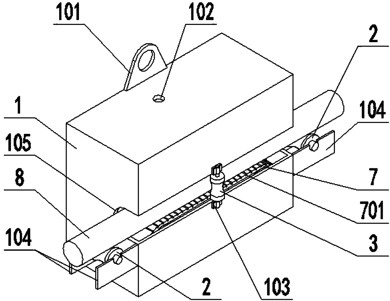
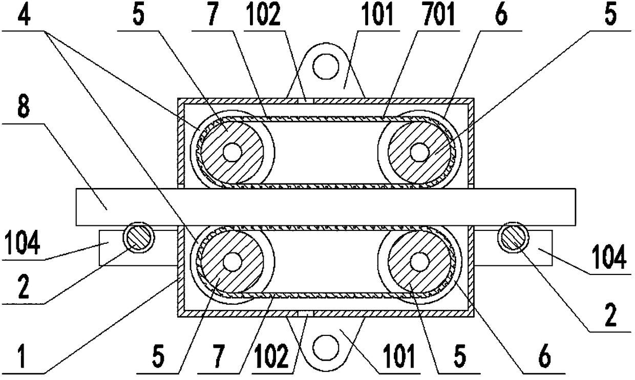
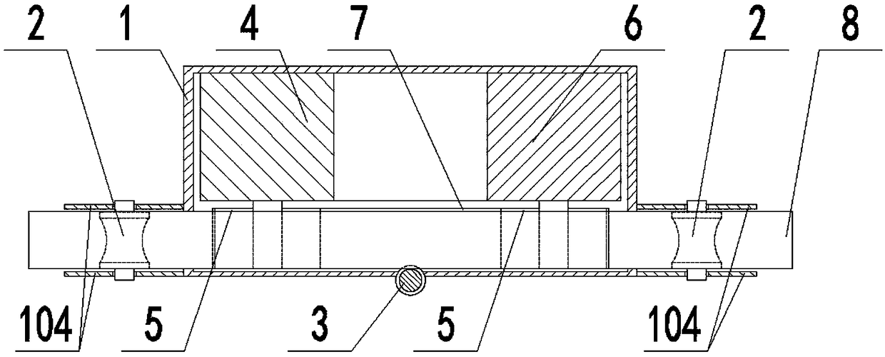
[0015] Such as Figure 1 ~ Figure 3 As shown, a mining cable laying device provided by the present invention includes a casing 1, idler roller I2, idler roller II3, air motor 4, pulley 5, support seat 6, and belt 7. The upper part of the casing 1 A hanging ear 101 and a through hole 102 are provided on the side and the lower side, a fixing seat 103 and a U-shaped groove 105 are provided on the front side of the housing 1, and two The bracket 104 is provided with a pulley 5 on the front side of the air motor 4 , and a groove 701 is provided on the belt 7 .

[0016] Preferably, idler rollers I2 are provided on the brackets 104 on the left and right sides of the housing 1 .

[0017] Preferably, an idler roller II3 is provided on the fixed seat ...


PUM


Abstract

The invention discloses a mine cable laying device. The mine cable laying device comprises a shell, a carrier roller I, a carrier roller II, a pneumatic motor, a belt pulley, a support seat, and a belt; a hanger and a through hole are formed on each of the upper side and the lower side of the shell; a fixed seat and a U-shaped slot are arranged at the front side of the shell; two brackets are arranged at each of the left side and the right side of the shell; the belt pulley is arranged at the front side of the pneumatic motor, and a groove is formed on the belt. By adopting the pneumatic motorstructure disclosed by the invention, when laying the cable, the manpower input is reduced, the manpower labor intensity is reduced, and the construction period is shortened; the friction between thebelt and the cable is increased due to the groove on the belt, the security coefficient is improved; and the laying device has the advantages of being simple in structure, convenient for operation, and low in cost.

Description

technical field [0001] The invention relates to the field of coal mine cable laying tools, in particular to a mine cable laying device. Background technique [0002] The driving of equipment in fully mechanized coal mining face is inseparable from power supply, and the laying of cables in the power supply system is a very important link. When using traditional manual laying of cables, it not only needs a lot of labor, labor intensity, time-consuming and laborious, but also It is not conducive to fast installation requirements, and the safety factor is low. Contents of the invention [0003] The object of the present invention is to provide a mining cable laying device, which adopts an air motor structure, which not only reduces the labor input and labor intensity, but also shortens the construction period when laying cables. The groove increases the frictional force between the belt and the cable, improves the safety factor, and also has the advantages of simple structure...

Claims


Application Information

Patent Timeline
IPC IPC(8): H02G1/06
CPCH02G1/06
Inventor 谢春虎张西洋储伟建王磊崔骄建
Owner ANHUI UNIV OF SCI & TECH
Why Eureka
Try Eureka