Method for achieving directional solidification based on 3D printing of multi-layer hollow shell mold

A 3D printing and directional solidification technology, applied in the direction of casting mold, core, casting mold composition, etc., can solve the problems of reducing casting performance, low cooling speed, affecting casting quality, etc., to improve casting pass rate, reduce miscellaneous crystals, The effect of optimizing the quality of castings and their properties

Active Publication Date: 2018-11-06
TSINGHUA UNIV
View PDF9 Cites 5 Cited by
  • Summary
  • Abstract
  • Description
  • Claims
  • Application Information

AI Technical Summary

Benefits of technology

This patented describes an improved way to make high strength materials more efficiently during production without causing issues like cracks or other imperfections caused when traditional ways involve melting them down. By utilising this new technique, there may also improve their properties even further.

Problems solved by technology

The technical problem addressed by this patented method relates to improving the efficiency of producing high-quality precision engine blade parts through controlled solidifying techniques that avoid excessive energy input or damage caused during production processes.

Method used


Image

  • Method for achieving directional solidification based on 3D printing of multi-layer hollow shell mold

Examples


Embodiment Construction

[0014] The method for realizing directional solidification based on 3D printing multi-layer hollow shells according to the present invention will be described in detail below with reference to the accompanying drawings.

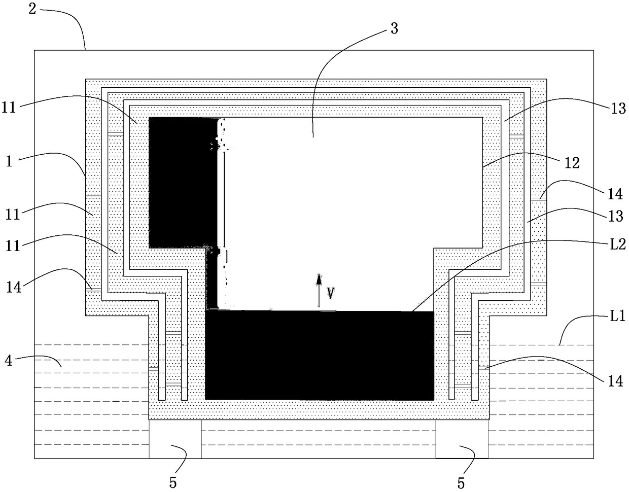
[0015] refer to figure 1 , according to the method for realizing directional solidification based on 3D printing multilayer hollow shell mold of the present invention, comprising step: S1, according to the casting to be cast, obtain the multilayer hollow shell mold structure 1 as the mold based on 3D printing technology, so The multi-layer hollow shell structure 1 includes a plurality of nested shells 11, the innermost shell 11 forms a cavity 12, and a hollow layer 13 is formed between two adjacent shells 11, except for the innermost Other shells 11 outside the shell are all provided with a plurality of through holes 14 evenly distributed in the vertical direction for communicating with the hollow layer 13; S2, the multilayer hollow shell structure 1 obtained in


PUM

PropertyMeasurementUnit
Thicknessaaaaaaaaaa

Abstract

The invention provides a method for achieving directional solidification based on 3D printing of a multi-layer hollow shell mold. The multi-layer hollow shell mold structure serving as a casting moldis suitable for casting a casting through directional solidification due to the excellent cooling capability, but the multi-layer hollow shell mold structure is complex, manufacturing is difficult through a conventional method, and the accurate multi-layer hollow shell mold structure can be manufactured on the basis of printing of the 3D printing technology. When the casting is cast, after liquidmetal is poured into a cavity of the multi-layer hollow shell mold structure, the bottom of the multi-layer hollow shell mold structure is immersed in cooling water to be cooled, directional solidification is formed, along with ascending of the cooling water liquid level, the hollow layer is gradually filled with the cooling water from bottom to top, the liquid metal solidification interface is gradually upwards pushed in the vertical direction under the situation that the height of the liquid metal solidification interface is larger than the cooling water liquid level height, the same heat preservation conditions of various positions of the casting and stable directional solidification are achieved, accordingly, the defects of mixed crystals, spots and the like are reduced, and the purposes that the casting quality and performance are optimized, and the casting qualification rate is increased are achieved.

Description


Claims


Application Information

Patent Timeline
Owner TSINGHUA UNIV
Why Eureka
Try Eureka