Numerical control shot-peening laser tool aligning device and method

A laser and shot peening technology, which is applied in metal processing equipment, used abrasive processing devices, manufacturing tools, etc., can solve problems such as nozzle inner diameter wear, affecting knife accuracy, etc., to improve knife setting accuracy and good linearity Effect

Inactive Publication Date: 2018-11-06
XIAN AIRCRAFT IND GROUP
View PDF6 Cites 1 Cited by
  • Summary
  • Abstract
  • Description
  • Claims
  • Application Information

AI Technical Summary

Problems solved by technology

The disadvantages of this method are: 1) the tool bar is bent due to its own weight during use, which affects the accuracy of tool setting; 2) when the nozzle is moved, the tool bar will interfere with the tooling and the workpiece; 3) the plug-in clamping method will cause wear on the inner diameter of the nozzle

Method used


Image

  • Numerical control shot-peening laser tool aligning device and method
  • Numerical control shot-peening laser tool aligning device and method
  • Numerical control shot-peening laser tool aligning device and method

Examples


Example Embodiment

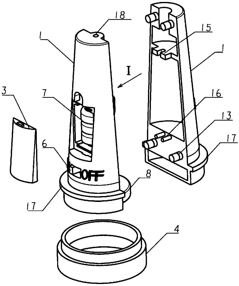
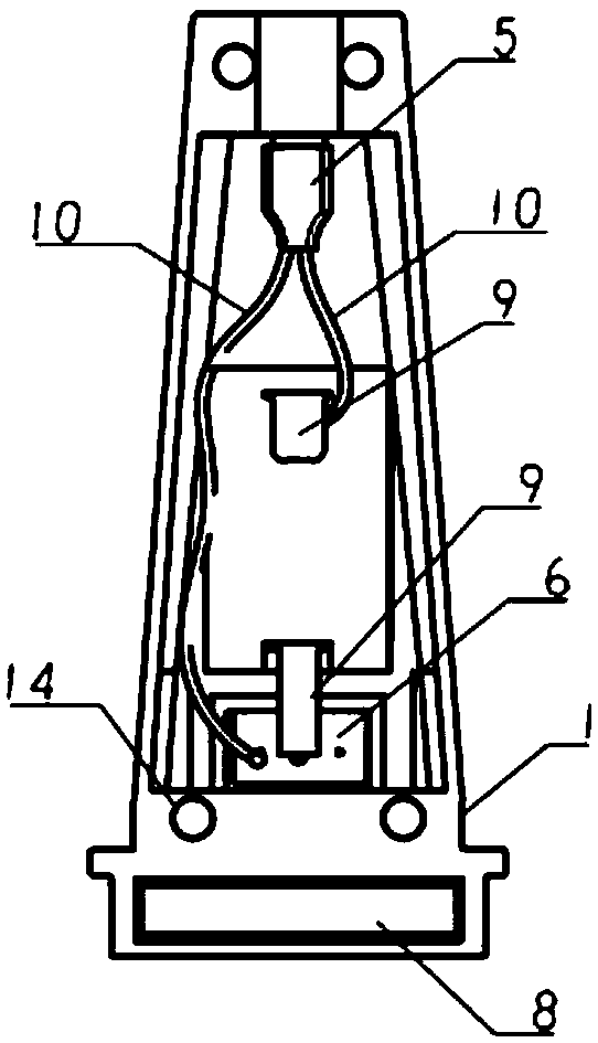
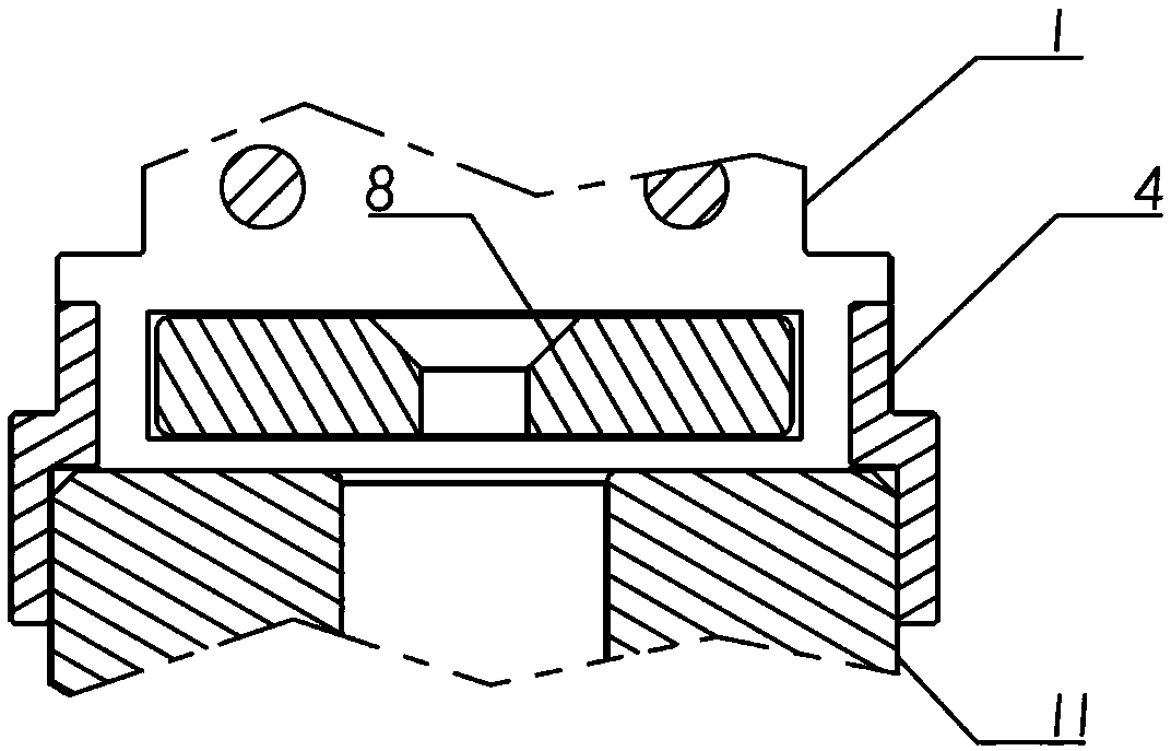
[0015] Depend on figure 1 As shown in -3, a laser tool setting device for CNC shot peening processing, including a housing 1, a semiconductor laser module 5, a battery 7, a magnet 8, and a limit sleeve 4, is characterized in that the housing is composed of left and right The half shell and the battery cover are combined, the top of the shell is provided with a laser outlet 18, the magnet 8 is installed at the bottom of the shell, the semiconductor laser module 5 and the battery 7 are installed inside the shell 1; the semiconductor laser module is composed of The semiconductor laser diode and the constant current drive circuit board are connected in series, and the laser is controlled and emitted by the switch, and the laser passes through the laser exit 18 to form a spot-like spot; the limit sleeve 4 is installed between the nozzle 11 and the shell 1 of the numerical control shot peening device, The limit sleeve 4 is a nested ring structure, the inner diameter of the upper ring i


PUM


Abstract

The invention provides a numerical control shot-peening laser tool aligning device and method. The tool aligning device comprises a shell, a semiconductor laser module, a battery, a magnet and a limiting sleeve. The semiconductor laser module emits laser. The relative positions of the shell and a nozzle are limited through the limiting sleeve, so that a laser optical path is consistent with the central axis of the nozzle. During usage, a switch is turned on, laser is emitted from a laser emitting port, the position of the nozzle is adjusted, thus, laser spots fall on a set tool start point, the tool start point is set as a machining origin, and tool aligning of the nozzle is completed. Through the device and method, the tool aligning accuracy is improved, and the problems of tool aligninginterference and application abrasion are avoided.

Description


Claims


Application Information

Patent Timeline
Owner XIAN AIRCRAFT IND GROUP
Why Eureka
Try Eureka