Automatic guided vehicle

An automatic guided vehicle and vehicle body technology, applied in the direction of motor vehicles, vehicle components, non-electric variable control, etc., can solve problems such as poor steering, and achieve the effect of flexible steering

Inactive Publication Date: 2019-01-04
HONG FU JIN PRECISION IND (SHENZHEN) CO LTD +1
View PDF5 Cites 2 Cited by
  • Summary
  • Abstract
  • Description
  • Claims
  • Application Information

AI Technical Summary

Benefits of technology

The present in this patented technology allows for flexible turning movement through an automated guide system used within vehicles without requiring manual operation or physical effort from operators. This makes it more efficient than traditional methods like hydraulics or pneumatics systems.

Problems solved by technology

The technical problem addressed by this patented solution for providing an automated guide system that can turn around freely without being affected or losing its effectiveness due to lack of stability during use.

Method used


Image

  • Automatic guided vehicle
  • Automatic guided vehicle

Examples


Embodiment Construction

[0043] The present invention will be further described in detail below in conjunction with the accompanying drawings.

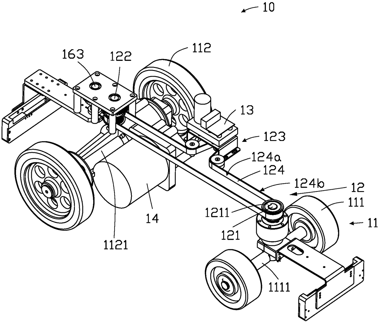
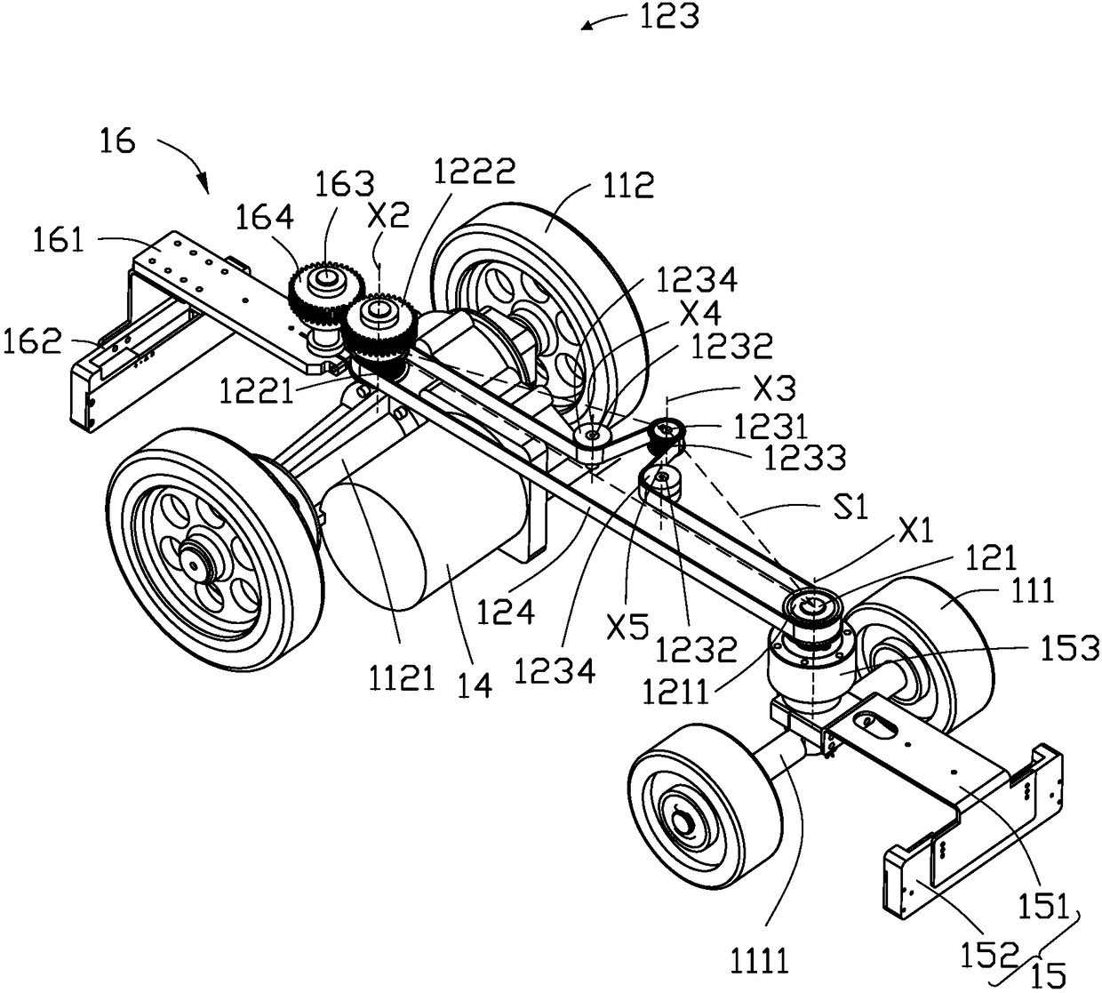
[0044] see Figure 1-2 , the present invention provides an automatic guided vehicle 10 . The automatic guided vehicle 10 includes a body part 11 , a steering part 12 , a control part 13 and a driving part 14 .

[0045] The vehicle body 11 includes two front wheels 111 and two rear wheels 112 . The vehicle body part 11 also includes supporting structures such as a chassis (not shown in the figure) and a compartment (not shown in the figure). A front wheel shaft 1111 is connected between the two front wheels 111 , and a rear wheel shaft 1121 is connected between the two rear wheels 112 . In this embodiment, the outer peripheries of the two front wheels 111 and the two rear wheels 112 are made of rubber.

[0046] The driving part 14 is disposed on the rear wheel shaft 1121 , and the driving part 14 drives the rear wheel shaft 1121 to rotate, thereby driving the


PUM


Abstract

An automatic guided vehicle comprises a vehicle body part and a steering part, wherein the vehicle body part comprises two front wheels and two rear wheels; the front wheel axle is connected between the two front wheels; and the rear wheel axle is connected between the two rear wheels. The steering part comprises a front steering shaft with a front gear sleeve on the outer periphery, a rear steering shaft with a first rear gear sleeve on the outer periphery, a steering drive and a conveyor belt. The steering part comprises a front steering shaft with a front gear sleeve on the outer periphery,and a rear steering shaft with a first rear gear sleeve on the outer periphery. The steering drive comprises a rotating shaft sleeved with a rotating gear on an outer periphery and a transmission shaft sleeved with a transmission gear on two outer peripheries respectively. The conveyor belt is sleeved with the front gear, the first rear gear and the rotating gear. The front gear, the first rear gear and the rotary gear are abutted against the inside of the conveyor belt, and the two transmission gears are abutted against the outside of the conveyor belt. Two transmission gears are located onboth sides of the rotating gear. The control part controls the rotation of the driving gear, and the driving gear drives the front gear, the rear gear and the two transmission gears to rotate.

Description


Claims


Application Information

Patent Timeline
Owner HONG FU JIN PRECISION IND (SHENZHEN) CO LTD
Why Eureka
Try Eureka