Side light-emitting deep-ultraviolet LED packaging bracket and production process thereof

A technology of LED packaging and production process, which is applied in the direction of semiconductor devices, electrical components, circuits, etc., can solve problems such as limitations, achieve the effect of improving service life, improving heat dissipation, and not easy to fall off

Active Publication Date: 2019-01-04
江西力特康光学有限公司
View PDF7 Cites 3 Cited by
  • Summary
  • Abstract
  • Description
  • Claims
  • Application Information

AI Technical Summary

Benefits of technology

The technical feature described in this patented technology relates to improving the performance of an emitted type semiconductor laser (LED) package brace. By adding a cerarnite or other insulating layer onto one face of the support structure instead of just covering it completely, we aimed towards achieving better cooling efficiency without affecting any important aspects like lens design. This results in longer lifespan and higher reliability of the LED device's operation compared to traditional designs. Additionally, the use of specific materials allows for improved mechanical properties such as reduced weight and increased durability while maintaining good optical characteristics. Overall, these improvements result in enhanced functionality and usableness of the emitter type LED packages.

Problems solved by technology

This patented technology relates to improving the efficiency and effectiveness of producing high brightness nitrogen (N) diodes that have unique properties when excited from UV rays emitted through fluorescent lamps. One solution involves creating a specialized brace called a "packet," where certain parts of the device are placed inside another part while still being protected against damage during manufacturing steps like heat treatments. By placing these components within one bag instead of separately, there will be fewer constraints than previously needed due to their separate nature. Additionally, if multiple devices require lights directed differently, each component needs to receive signals individually controlling them independently without affecting other components.

Method used


Image

  • Side light-emitting deep-ultraviolet LED packaging bracket and production process thereof
  • Side light-emitting deep-ultraviolet LED packaging bracket and production process thereof
  • Side light-emitting deep-ultraviolet LED packaging bracket and production process thereof

Examples


Embodiment Construction

[0036] Various exemplary embodiments of the present invention will now be described in detail with reference to the accompanying drawings. It should be noted that the relative arrangements of components and steps, numerical expressions and numerical values ​​set forth in these embodiments do not limit the scope of the present invention unless specifically stated otherwise.

[0037] The following description of at least one exemplary embodiment is merely illustrative in nature and in no way taken as limiting the invention, its application or uses.

[0038] Techniques, methods and devices known to those of ordinary skill in the relevant art may not be discussed in detail, but where appropriate, such techniques, methods and devices should be considered part of the description.

[0039] In all examples shown and discussed herein, any specific values ​​should be construed as exemplary only, and not as limitations. Therefore, other instances of the exemplary embodiment may have differ


PUM


Abstract

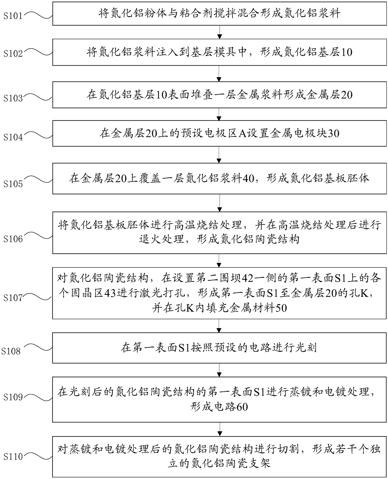
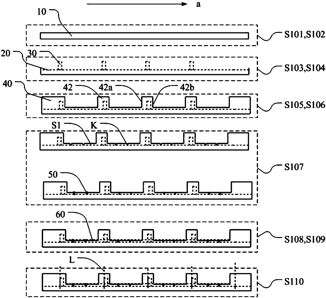
The invention discloses a side light-emitting deep ultraviolet LED packaging bracket and a production process thereof, the production process includes forming aluminum nitride slurry, injecting it into a base layer mold to form an aluminum nitride base layer; forming a metal layer on the surface of the aluminum nitride base layer; arranging a metal electrode block in a preset electrode region on the metal layer; covering layer of aluminum nitride paste on the metal layer to form an aluminum nitride substrate embryo body; The aluminum nitride substrate embryo is sintered and annealed at high temperature to form an aluminum nitride ceramic structure; The aluminum nitride ceramic structure is laser drilled in each die bonding region on the first surface on the side of the second enclosure damto form a hole from the first surface to the metal layer, and the hole is filled with a metal material; A circuit is formed by photolithography on the first surface according to a preset circuit, anda plurality of independent aluminum nitride ceramic supports are formed after cutting. By the invention, the deep ultraviolet LED lateral light emission can be realized.

Description


Claims


Application Information

Patent Timeline
Owner 江西力特康光学有限公司
Why Eureka
Try Eureka