Wire rod, steel wire, and part

A wire rod and steel wire technology, applied in the field of wire rod, can solve the problems of inability to obtain cold forgeable mechanical parts, inability to obtain cold forgeability, poor cold forgeability, etc.

Active Publication Date: 2019-02-05
NIPPON STEEL CORP
View PDF7 Cites 0 Cited by
  • Summary
  • Abstract
  • Description
  • Claims
  • Application Information

AI Technical Summary

Benefits of technology

The technical effect that this technology can be applied for making small components made from materials like aluminum or steel without adding too much material makes them lighter than traditional ones while still maintaining their high level of durability.

Problems solved by technology

The technical problem addressed in this patented text relates to improving the performance of machinery made from advanced material technologies (AMTs) without increasing their costs through complex processes involving multiple steps during production process. Specifically, current techniques involve expensive equipment and slow down overall productivity while also requiring strict controls over time and quality standards.

Method used


Image

  • Wire rod, steel wire, and part
  • Wire rod, steel wire, and part
  • Wire rod, steel wire, and part

Examples


Embodiment

[0100] Next, examples of the present invention will be described, but the conditions in the examples are examples of conditions adopted for confirming the practicability and effects of the present invention, and the present invention is not limited to the examples of conditions. The present invention can employ various conditions as long as the object of the present invention is achieved without departing from the gist of the present invention.

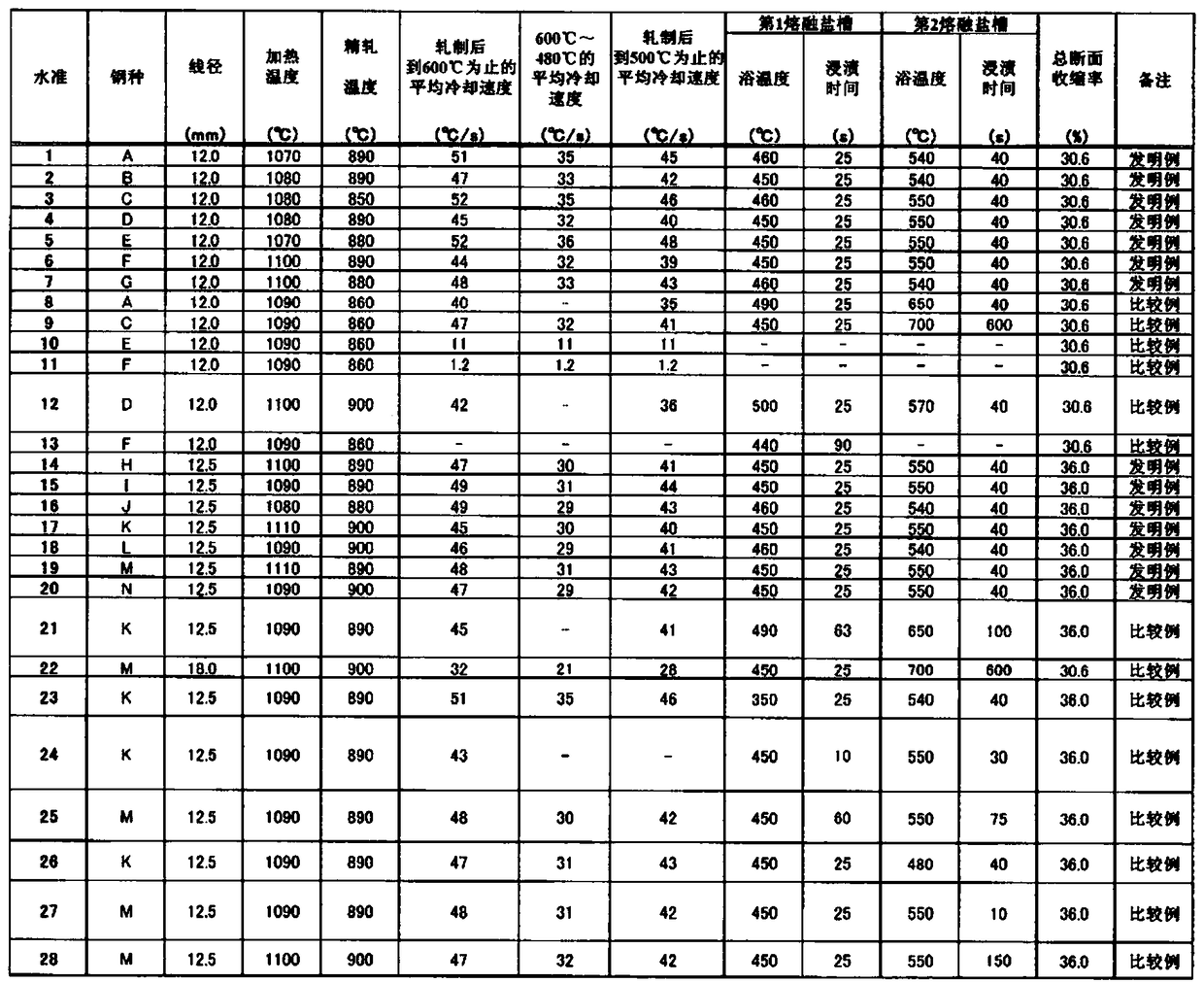
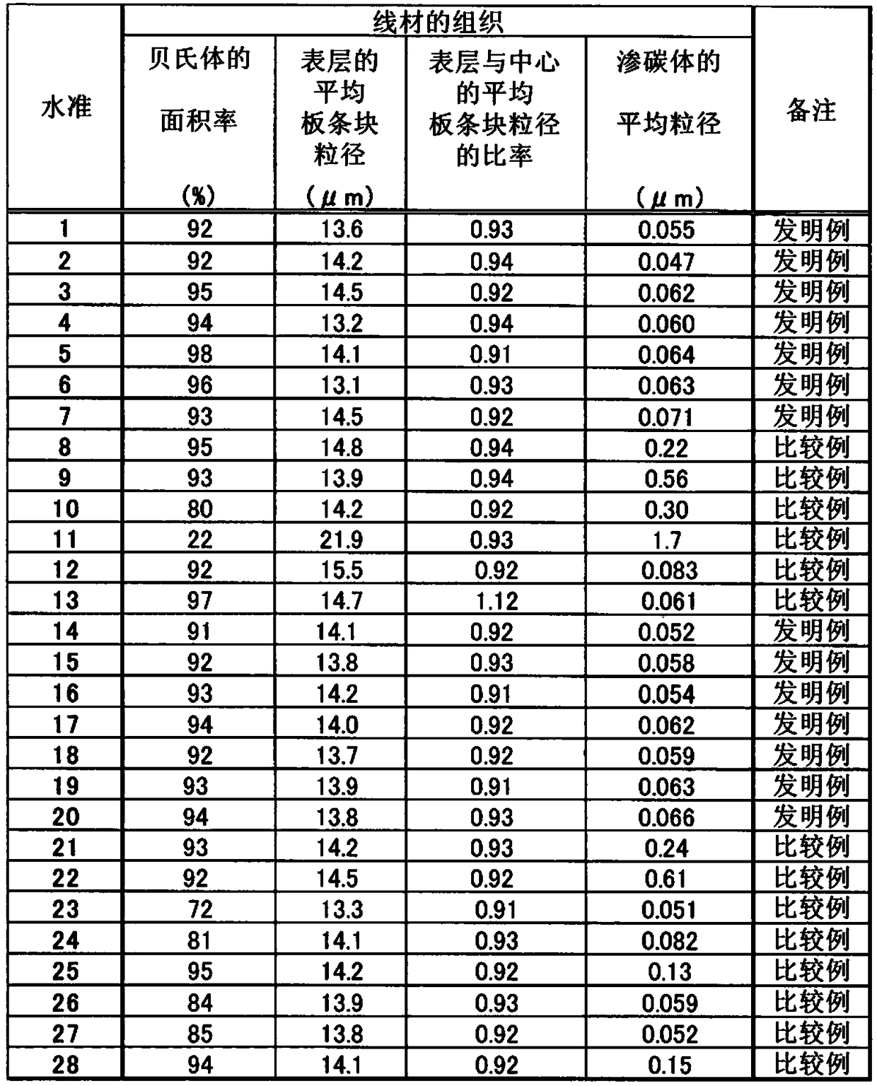
[0101] Using billets with the 14 compositions shown in Table 1, under the conditions of the 28 modes shown in Table 2, heating, hot rolling, constant temperature phase transformation treatment, and cooling were sequentially performed to manufacture wire rods (levels 1 to 28) ). Next, each wire rod was subjected to wire drawing at the reduction of area shown in Table 2 to manufacture steel wires (levels 1 to 28). Furthermore, using each steel wire, the sample whose height was 1.5 times the diameter was produced by machining, and componen


PUM


Abstract

Provided are a wire rod, etc. for which spheroidize annealing and quenching/tempering heat treatment steps can be omitted. The wire rod has a specified chemical composition. In area ratio, at least 90% of the metal structure is bainite. The average bainite block grain diameter in the surface layer measured in a transverse cross-section is 15 Mum or less. The ratio between the average bainite blockgrain diameter in the surface layer measured in a transverse cross-section and the average bainite block grain diameter measured in the center section is less than 1.0, and the average grain diameterof cementite dispersed in the bainite is 0.1 Mum or less.

Description


Claims


Application Information

Patent Timeline
Owner NIPPON STEEL CORP
Why Eureka
Try Eureka