Brick lifting device for construction site

A technology for construction sites and bricks, applied in the field of lifting construction site devices, can solve problems such as unfavorable promotion and popularization, complex lifting device structure, etc., and achieve the effects of simple and reliable structure, small footprint and high flexibility

Inactive Publication Date: 2019-03-29
缙云县乾恒商贸有限公司
View PDF1 Cites 0 Cited by
  • Summary
  • Abstract
  • Description
  • Claims
  • Application Information

AI Technical Summary

Problems solved by technology

[0004] Although the above-mentioned lifting device for construction can be used to lift stone materials for construction, the struc

Method used


Image

  • Brick lifting device for construction site
  • Brick lifting device for construction site
  • Brick lifting device for construction site

Examples


Embodiment Construction

[0032] The technical solutions in the present invention will be clearly and completely described below in conjunction with the accompanying drawings in the embodiments of the present invention. Obviously, the described invention is only a part of the embodiments of the present invention, not all of them. Based on the embodiments of the present invention, all other embodiments obtained by persons of ordinary skill in the art without making creative efforts belong to the protection scope of the present invention.

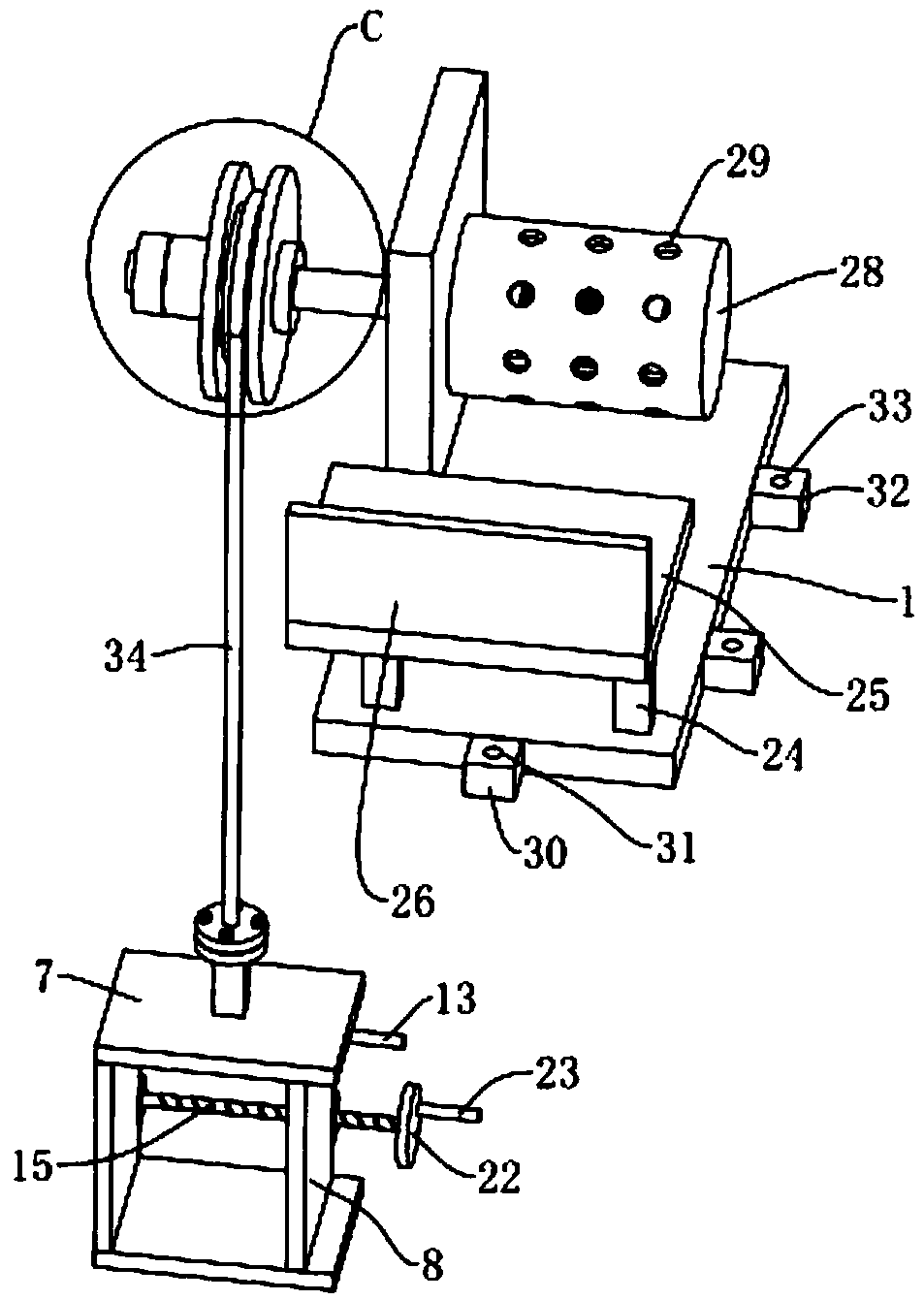
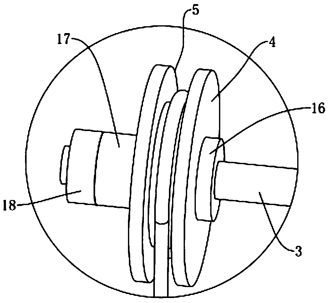
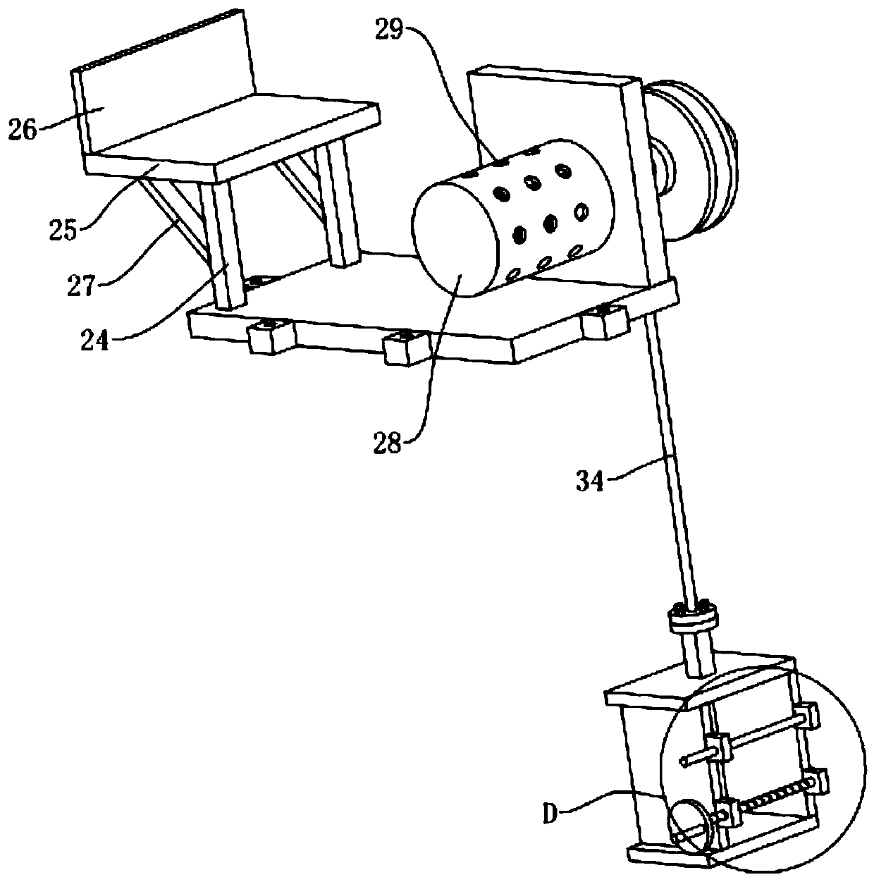
[0033] Such as Figure 1 to Figure 6 As shown, a lifting device for bricks on a construction site includes a frame 1, wherein a servo motor 2 is fixed on the frame 1, and a first fixed rod 3 is fixed on the motor shaft of the servo motor 2, wherein the first fixed The rod 3 is disassembled and connected with the wheel 4 through the first connecting part, and the wheel 4 can be fixed on the first fixed rod 3 through the first connecting part. At the bottom of the groove


PUM


Abstract

The invention discloses a brick lifting device for a construction site. The brick lifting device is characterized in that a rack is included; a servo motor is fixed to the rack; a first fixed rod is fixed to a motor shaft of the servo motor and detachably connected with a wheel disc through a first connecting part; the wheel disc is provided with a groove for coiling a steel wire rope; one end ofthe steel wire rope is fixed to the groove bottom of the groove; the end, away from the wheel disc, of the steel wire rope is detachably connected with a second fixing rod through a second connectingpart; a [-shaped plate is fixed to the end of the second fixing rod; an opening of the [-shaped plate is slidably connected with a first baffle; a first fixed block and a second fixed block are fixedto the [-shaped plate; and a third fixed block and a fourth fixed block are fixed to the first baffle. The brick lifting device for the construction site has the characteristics of simple and reliablestructure and stable lifting, and is small in occupied area, high in flexibility and high in practicability.

Description


Claims


Application Information

Patent Timeline
Owner 缙云县乾恒商贸有限公司
Why Eureka
Try Eureka