High-precision Rogowski coil
A Rogowski coil and compensation coil technology, applied in the direction of coils, voltage/current isolation, electrical components, etc., can solve the problem of misalignment between the central axis of the wire and the central axis of the Rogowski coil, saving installation time, reducing the time for the alignment process, Good centering effect
- Summary
- Abstract
- Description
- Claims
- Application Information
AI Technical Summary
Problems solved by technology
Method used
Image

Examples
Example Embodiment
[0019] Example one:
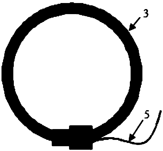
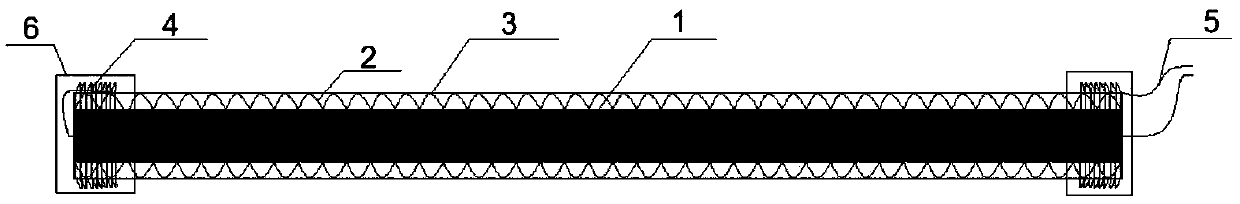
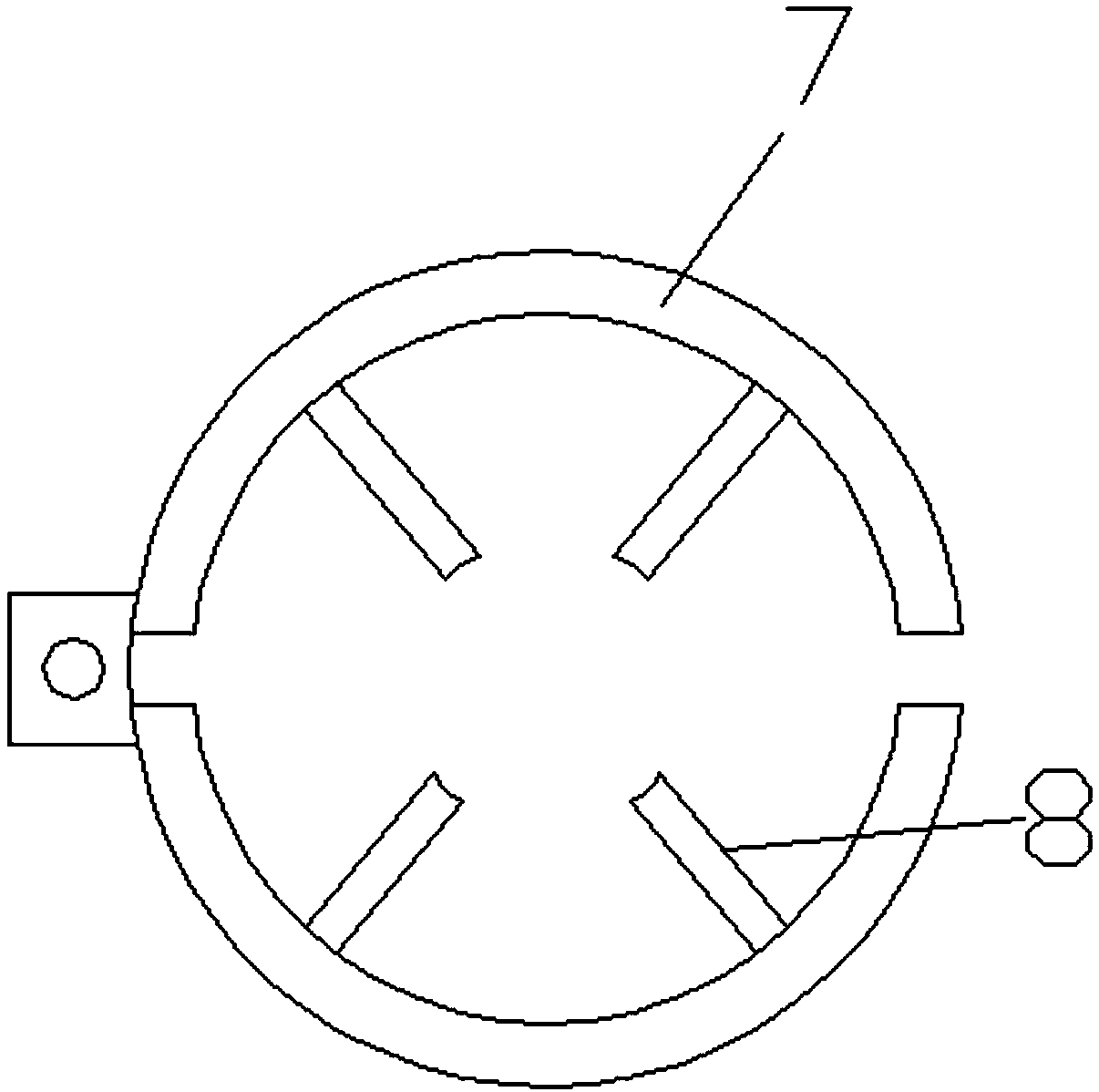
[0020] Such as Figure 1 to Figure 3 As shown, the present invention is a Rogowski coil, including an ignition wire 1, an enameled wire 2 and a silicone tube 3 arranged in sequence from the inside to the outside. The enameled wire 2 is wound on the ignition wire 1, the ignition wire 1 and the enameled wire The two ends of 2 are connected by a joint 6. The joint 6 is provided with a compensation coil 4 and a lead wire 5. One end of the compensation coil 4 is connected to the enameled wire 2 and the other end is connected to the lead wire 5; the ignition wire 1 is provided with a skeleton 7 inside the ring, The inner wall of the frame 7 is provided with a wire Rogowski coil centering mechanism. The centering mechanism includes four airbags 8 arranged in a circular array with the center of the Rogowski coil fixed on the inner wall of the frame 7. The outer shell of the airbag 8 is made of elastic rubber, and the outer shell of the airbag 8 is cylindrical and arran
Example Embodiment
[0021] Embodiment two:
[0022] The difference from the first embodiment is that Figure 4 As shown, the centering mechanism includes four sleeves 9 arranged in a circular array with the center of the Rogowski coil fixedly arranged on the inner wall of the frame 7. The sleeve 9 is fitted with a sliding column 10, and the sliding column 10 is connected to the sleeve through a spring 11 9 is connected to the bottom wall, the space between the sliding column 10 and the bottom wall of the sleeve 9 is provided with two elastic liquid-filled columns 12, the spring 11 is located between the two elastic liquid-filled columns 12, the elastic liquid-filled column 12 and the liquid-filled tube 13 The filling tube 13 is connected to the liquid storage tank 14 through a hydraulic pump. The end of the sliding column 10 close to the center of the Rogowski coil is fixedly provided with an inflatable bag 15. The shell of the inflatable bag 15 is made of hard material, and the inflatable bag 15 is clo
Example Embodiment
[0023] Embodiment three:
[0024] The difference from the first embodiment is that Figure 5 to Figure 7 As shown, the centering mechanism includes an L-shaped centering plate 19 fixed on the inner wall of the ring of the frame 7. The vertical plate 20 and the horizontal plate 21 of the centering plate 19 are respectively fixedly connected to the frame 7 by connecting rods 22. One side of the plate 20 is located on the diameter of the ring frame 7, and the middle of the vertical plate 20 is located at the center of the Rogowski coil with a first semicircular notch 23. The radius of the first semicircular notch 23 is the same as that of the wire to be measured. The radii are matched. The end of the vertical plate 20 close to the frame 7 is provided with a groove plate 24 with a sliding groove. The groove plate 24 is arranged in parallel with the transverse plate 21 of the centering plate 19, and a rectangular plate 25 is slidably arranged in the groove plate 24. The side of the rect
PUM
 Abstract
Description
Claims
Application Information
 - R&D Engineer
- R&D Manager
- IP Professional
- Industry Leading Data Capabilities
- Powerful AI technology
- Patent DNA Extraction
Browse by: Latest US Patents, China's latest patents, Technical Efficacy Thesaurus, Application Domain, Technology Topic.
© 2024 PatSnap. All rights reserved.Legal|Privacy policy|Modern Slavery Act Transparency Statement|Sitemap