Electromagnetic force vibration device

A vibration excitation device and electromagnetic excitation technology, applied in the direction of measuring devices, high-efficiency power electronic conversion, output power conversion devices, etc., can solve the problems of being difficult to provide non-contact, insufficiently accurate test results, and low error , to achieve fast dynamic response, achieve the effect of low condition requirements and low error

Active Publication Date: 2019-04-16
TIANJIN UNIV
View PDF7 Cites 0 Cited by
  • Summary
  • Abstract
  • Description
  • Claims
  • Application Information

AI Technical Summary

Problems solved by technology

[0002] In the field of engineering vibration testing, in order to study the dynamic behavior and characteristics of one-dimensional nonlinear systems, computer

Method used


Image

  • Electromagnetic force vibration device
  • Electromagnetic force vibration device
  • Electromagnetic force vibration device

Examples


Example Embodiment

[0019] The problem to be solved by the present invention is to provide a vibration experiment device excited by electromagnetic force to provide non-contact and low-frequency sinusoidal excitation force with low enough error for various one-dimensional vibrator test benches, so as to effectively observe The dynamic behavior and characteristics of one-dimensional oscillators in the case of external conditions and excitation forms.

[0020] The present invention solves its technical problem and realizes by taking the following technical solutions:

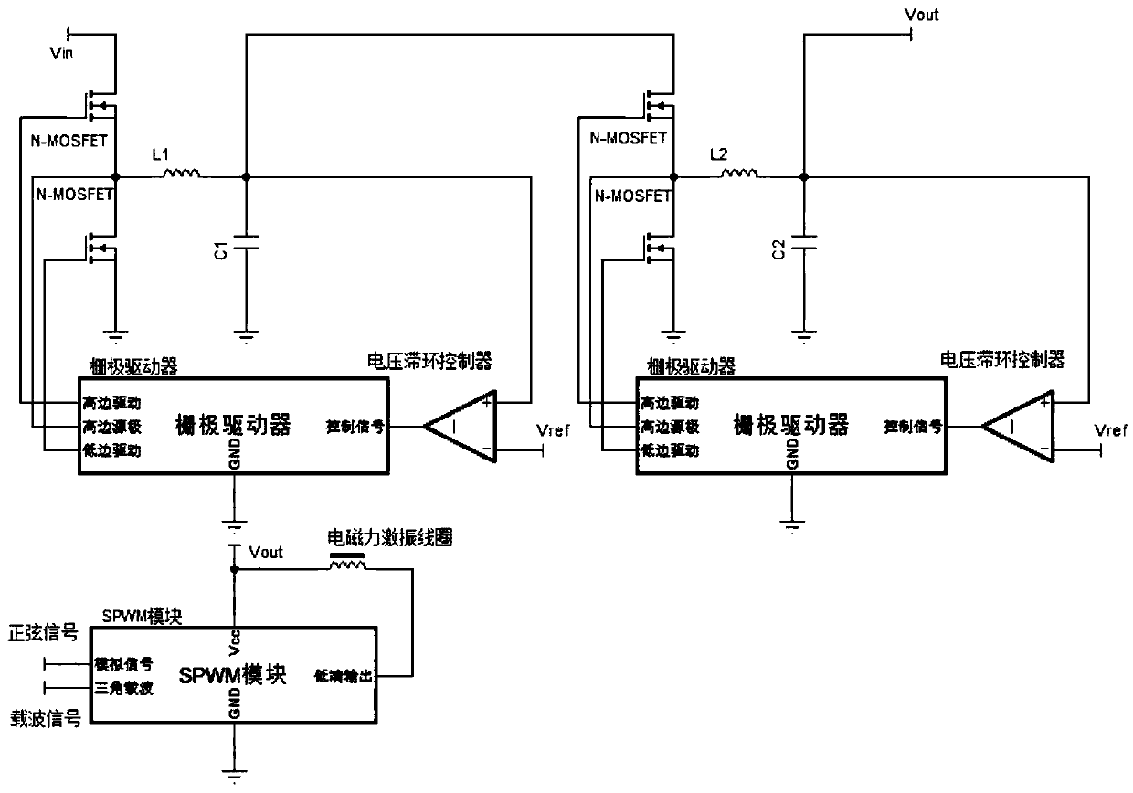
[0021] An electromagnetic force excitation device provided according to the present invention includes a set of high-voltage Buck circuits, a set of low-voltage Buck circuits, a set of analog signal pulse width modulation circuits, and a set of electromagnetic excitation coils.

[0022] like figure 1 As shown, the input terminal of the high-voltage Buck circuit is connected to the 220V AC that has been rectified, filtered and power fac


PUM


Abstract

The invention belongs to the field of dynamics control experiments and discloses an electromagnetic force vibration device which gives various one-dimensional vibrator experiment tables to provide non-contact low and medium frequency sine exciting force with pretty low errors, thus the dynamic behavior and characteristic of one-dimensional vibrators under the condition with different environmentsand incentive forms are effectively observed. The electromagnetic force vibration device includes a high-voltage Buck circuit, a low-voltage Buck circuit, an analog signal pulse width modulator circuit and an electromagnetic vibration coil, wherein the input end of the high-voltage Buck circuit accesses an alternating current of 220 V, the alternating current is compensated by waves filtering rectifier and power factor, the input end of the low-voltage Buck circuit is connected with the output end of the high-voltage Buck circuit, the input end of the pulse width modulator circuit is connectedwith the output end of the low-voltage Buck circuit, and the output end of the pulse width modulator circuit is connected with the electromagnetic vibration coil. The electromagnetic force vibrationdevice is mainly applied to situation of kinetic control and vibrator experiments.

Description


Claims


Application Information

Patent Timeline
Owner TIANJIN UNIV
Why Eureka
Try Eureka