Electric fuel, gaseous fuel and solid biomass fuel integrated heat furnace and using method

A technology of solid biomass and gas fuel, applied in heating methods, lighting and heating equipment, applications, etc., can solve the problems of single application of heat furnace energy, waste of resources, single function, etc., to reduce heat loss in advance and improve utilization efficiency , the effect of improving comfort

Active Publication Date: 2019-05-24
长阳清江农机制造有限公司
View PDF8 Cites 2 Cited by
  • Summary
  • Abstract
  • Description
  • Claims
  • Application Information

AI Technical Summary

Benefits of technology

In this design, there are three main components: an integration heater that uses both solid or liquid fuels (biomasse) while still being able to efficiently mix different forms of energy like burning wood pulp). An elevator system moves along rails within the furnaces' bodies to adjust their heights based on how much space they occupy. A circulation loop makes efficient usage of residual heat from flues compared to previous designs where all these materials were burnt separately. Additionally, a separate charger allows users to easily add new material when needed. Overall, this technology helps optimize energy utilization and reduces emissions during operation.

Problems solved by technology

This patented describes different types of stoveshires used worldwide including inductive or gas-fired stovhs with various technical features such as cost savings, improved fuel economy compared to traditional methods like coal fireplaces, reduced environmental impact due to emissions from burning fossil fuels, increased safety during operation by reducing potential hazards associated with uncontrolled emission. Additionally, it provides an efficient way to dispose waste gases generated through conventional sources without causing harm on human health concerns.

Method used


Image

  • Electric fuel, gaseous fuel and solid biomass fuel integrated heat furnace and using method
  • Electric fuel, gaseous fuel and solid biomass fuel integrated heat furnace and using method
  • Electric fuel, gaseous fuel and solid biomass fuel integrated heat furnace and using method

Examples


Embodiment 1

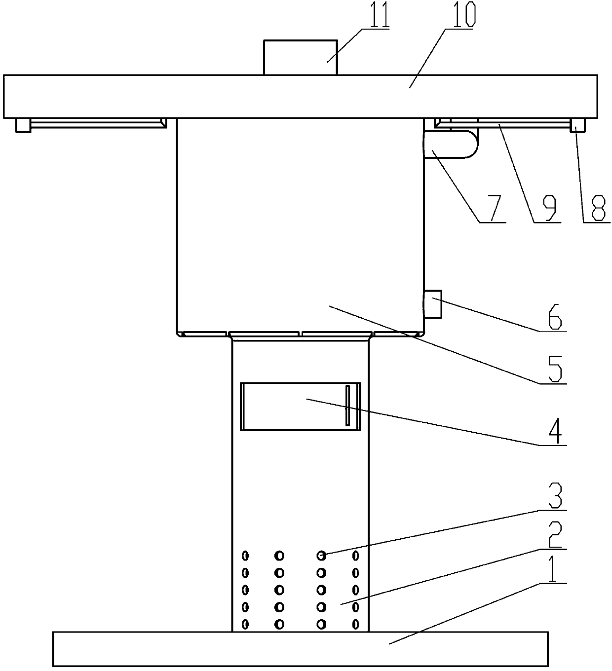
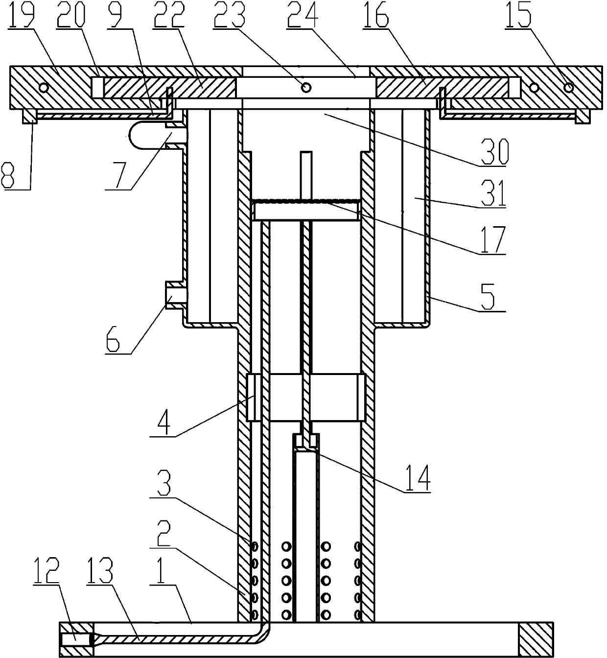
[0035] see Figure 1-8 , an integrated thermal furnace with electricity, gas fuel and solid biomass fuel, which includes a furnace base 1, a furnace body 2 is installed on the top of the furnace base 1, a furnace platform 10 is installed on the top of the furnace body 2, and the furnace body 2 is equipped with a lifting mechanism 14 at the bottom of the interior, the top of the lifting mechanism 14 is fixedly equipped with a furnace bridge 17, and the bottom of the furnace body 2 is provided with evenly distributed air intake honeycomb holes 3. A furnace door 4 is arranged on the outer wall; a combustion cavity 30 is formed between the top of the furnace bridge 17 and the furnace platform 10; the inside of the furnace platform 10 is fitted with an electromagnetic oven tray 22 for electric heating by sliding fit; the electromagnetic oven panel The opposite side of 22 is fitted with a support disc 16 by sliding fit; a gas heating structure is arranged inside the furnace body 2 . T

Embodiment 2

[0048] The use method of any one of the electric, gaseous fuel and solid biomass fuel integrated furnace:

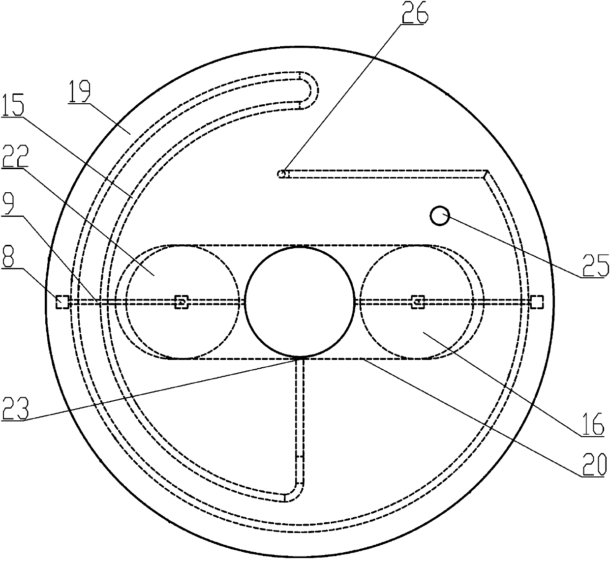
[0049] When the pure electric system is working, the above-mentioned slider 8 is manually pushed, the push rod 9 is pushed by the slider 8, and the above-mentioned electromagnetic hob 22 is pushed by the push rod 9 to move along the hob slide rail 20 to the position where the center hole 24 of the hob is located. , and then start the electromagnetic oven tray 22, and heat the pot through the electromagnetic oven tray 22;

[0050] When the pure gas system is working, the induction hob 22 is manually put away, and the above-mentioned support disc 16 is pushed along the hob slide rail 20 to the position where the center hole 24 of the hob is located, and the pot is placed on the support disc 16 , forming a semi-closed combustion chamber, the exhaust gas can only enter the flue 28 and the circulation coil 15, so as to realize the discharge of the exhaust gas and the heating of


PUM


Abstract

The invention discloses an electric fuel, gaseous fuel and solid biomass fuel integrated heat furnace and a using method. The electric fuel, gaseous fuel and solid biomass fuel integrated heat furnacecomprises a furnace seat, a furnace body is mounted at the top of the furnace seat, and a furnace table is installed at the top of the furnace body. A lifting mechanism is installed at the bottom endin the furnace body, and a furnace bridge is fixedly mounted at the top of the lifting mechanism. Uniformly distributed air inlet honeycomb holes are formed in the bottom of the furnace body, and a furnace door is arranged on the outer side wall of the furnace body. A combustion cavity is formed between the top of the furnace bridge and the furnace table. An induction cooker plate for electric heating is mounted in the furnace table through sliding fit. A support disc is mounted on the opposite side of the induction cooker plate through the sliding fit. A gas heating structure is disposed inthe furnace body. Through the integrated heat furnace of the above structure, the integrated heat furnace can heat by using electricity or gas, and can further use solid biomass fuel for heating, thereby greatly enhancing the adaptability and meeting different heating requirements.

Description


Claims


Application Information

Patent Timeline
Owner 长阳清江农机制造有限公司
Why Eureka
Try Eureka