Smart capturing device

A capture device and intelligent technology, applied in animal traps, applications, animal husbandry, etc., can solve the problems of low capture efficiency, no continuous capture, and inability to realize automatic continuous capture, etc., and achieve the effect of high capture efficiency and automatic continuous capture

Inactive Publication Date: 2019-05-31
李良杰
View PDF0 Cites 0 Cited by
  • Summary
  • Abstract
  • Description
  • Claims
  • Application Information

AI Technical Summary

Problems solved by technology

[0002] The existing capture device does not have the function of continuous capture. It needs manual intervention after a capture to continue to captur

Method used


Image

  • Smart capturing device

Examples


Embodiment Construction

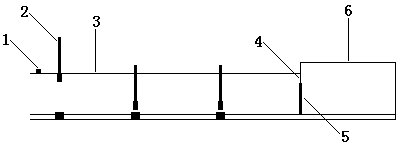
[0009] The intelligent capture device consists of a control switch (1), a channel (3), an electric control door (2), an ultrasonic sensor, a pressure sensor, a collection bin (6), a one-way spring (4), a collection bin door (5) and a microcomputer It consists of modules, the control switch is installed at the front end of the channel, there are multiple horizontal openings on the channel, the electric control door is installed in the opening above the channel, the rear end of the channel is equipped with a collection bin, and there is a collection bin between the channel and the collection bin. The bin door, the collection bin door is installed on the inner side of the upper wall of the passage through the one-way spring, the one-way spring only allows the collection bin door to open toward the collection bin, and the ultrasonic sensor is installed on the inner side of the passage side wall between the electric control door and the electric control door The pressure sensor is inst


PUM


Abstract

Provided is a smart capturing device. The smart capturing device is composed of a control switch, a channel, electric control doors, ultrasonic sensors, pressure sensors, a collection bin, a one-way spring, a collection bin door and a micro-computer module; the control switch is mounted at the front end of the channel, a plurality of transverse openings are formed in the channel, the electric control doors are arranged inside the opening in the channel, the collection bin is arranged at the rear end of the channel, the collection bin door is arranged between the channel and the collection binand is mounted at the inner side of the upper wall of the channel through the one-way spring, the one-way spring only allows the collection bin door to open in the direction of the collection bin, andthe ultrasonic sensors are mounted at the inner sides of the side walls of the portions, between the adjacent electric control doors, of the channel and at the inner side of the side wall of the portion, between the collection bin door and the adjacent electric control door, of the channel; the pressure sensors are mounted at the portions, between the adjacent electric control doors, of the bottom of the channel and at the portion, between the collection bin door and the adjacent electric control door, of the bottom of the channel; the signal output end of the control switch, the signal output ends of the ultrasonic sensors and the signal output ends of the pressure sensors are connected to the signal input end of the micro-computer module, and the signal input ends of the electric control doors are connected to the signal output end of the micro-computer module.

Description


Claims


Application Information

Patent Timeline
Owner 李良杰
Why Eureka
Try Eureka