Control circuit of smoke exhaust fan and smoke exhaust control system

A smoke exhaust fan and control circuit technology, applied in pump control, mechanical equipment, machine/engine, etc., can solve the problem of low reliability of smoke exhaust control, achieve the effect of improving reliability and reducing damage

Active Publication Date: 2019-05-31
CHINA ENERGY ENG GRP GUANGDONG ELECTRIC POWER DESIGN INST CO LTD
View PDF6 Cites 0 Cited by
  • Summary
  • Abstract
  • Description
  • Claims
  • Application Information

AI Technical Summary

Problems solved by technology

[0004] Based on this, it is necessary to provide a smoke exhaust fan control circuit and a smoke e

Method used


Image

  • Control circuit of smoke exhaust fan and smoke exhaust control system
  • Control circuit of smoke exhaust fan and smoke exhaust control system
  • Control circuit of smoke exhaust fan and smoke exhaust control system

Examples


Embodiment Construction

[0039] In order to facilitate the understanding of the present application, the present application will be described more fully below with reference to the relevant drawings. A preferred embodiment of the application is shown in the drawings. However, the present application can be embodied in many different forms and is not limited to the embodiments described herein. On the contrary, the purpose of providing these embodiments is to make the disclosure of this application more thorough and comprehensive.

[0040] It should be noted that when an element is considered to be "connected" to another element, it may be directly connected to and integrally integrated with the other element, or there may be an intervening element at the same time. The terms "first end", "second end" and similar expressions are used herein for the purpose of illustration only.

[0041] Unless otherwise defined, all technical and scientific terms used herein have the same meaning as commonly understood


PUM


Abstract

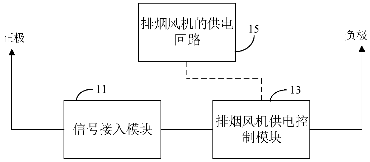
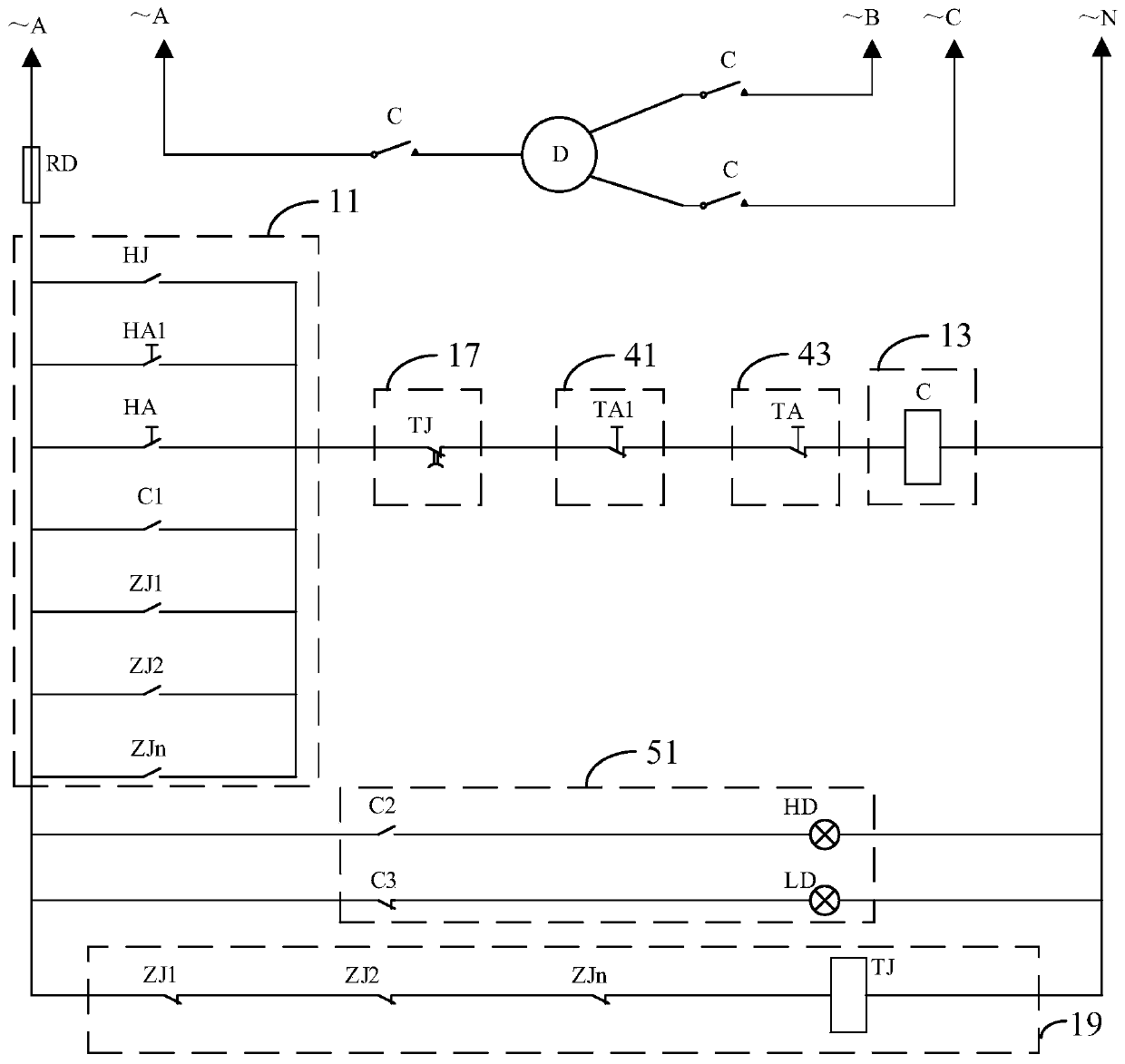
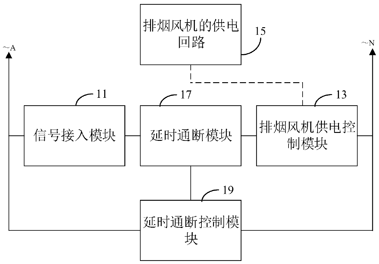
The invention relates to a control circuit of a smoke exhaust fan and a smoke exhaust control system. The control circuit of the smoke exhaust fan comprises a signal access module and a smoke exhaustfan power supply control module. The first end of the signal access module is connected with the first end of the smoke exhaust fan power supply control module, and the second end of the signal accessmodule is used for being connected with a positive electrode of a power source. The second end of the smoke exhaust fan power supply control module is used for being connected with a negative electrode of the power source. The signal access module is switched on when a fire alarm signal is received, so that a power supply loop of the smoke exhaust fan is switched on by the smoke exhaust fan powersupply control module based on electric energy of the power source. The fire alarm signal comprises a smoke exhaust valve switch-on signal sent by a smoke exhaust valve, and an automatic remote startsignal sent by an automatic fire alarming system or an artificial remote start signal sent by a fire alarm linkage control system. By means of the control circuit of the smoke exhaust fan and the smoke exhaust control system, the problem that the smoke exhaust fan cannot be started when the automatic fire alarming system and the fire alarm linkage control system break down can be avoided, and then the reliability of the smoke exhaust fan is improved.

Description


Claims


Application Information

Patent Timeline
Owner CHINA ENERGY ENG GRP GUANGDONG ELECTRIC POWER DESIGN INST CO LTD
Why Eureka
Try Eureka