Multifunctional sunlight room installation lifting machine

A sun room and multi-functional technology, applied in the direction of portable lifting devices, cranes, hoisting devices, etc., can solve the problems of inconvenient transportation, inconvenient disassembly of small cranes, unusable lifting equipment, etc., to improve stability and reliability, Avoid uneven weight distribution, convenient and fast installation and fixation

Pending Publication Date: 2019-10-08
何齐
View PDF0 Cites 2 Cited by
  • Summary
  • Abstract
  • Description
  • Claims
  • Application Information

AI Technical Summary

Benefits of technology

This innovative technology improves the performance of materials handling equipment used at construction sites such as cranes. It allows users to lift heavier objects more efficiently without tilting them excessively due to unstable weights distributed along their supports caused by uneven load distributions. Additionally, it provides an efficient way to install and securely hold the elevating apparatus while moving around underground. Overall, this new design enhances safety measures and reduces damage from falls and collision between machines and columns.

Problems solved by technology

This patents describes different types of smaller machines called minihocks (small hatchbacks) made by companies like LORD Technologies Inc., People's Laboratories). These devices have their own limitations when handling tall loads because they require extra support during use compared to other methods like hydraulic jacks. They may only hold lightweight things but lack stability against gravity forces caused by wind pressure. Additionally, these systems often involve complex structures requiring expensive construction processes at manufacture sites.

Method used


Image

  • Multifunctional sunlight room installation lifting machine
  • Multifunctional sunlight room installation lifting machine
  • Multifunctional sunlight room installation lifting machine

Examples


Embodiment Construction

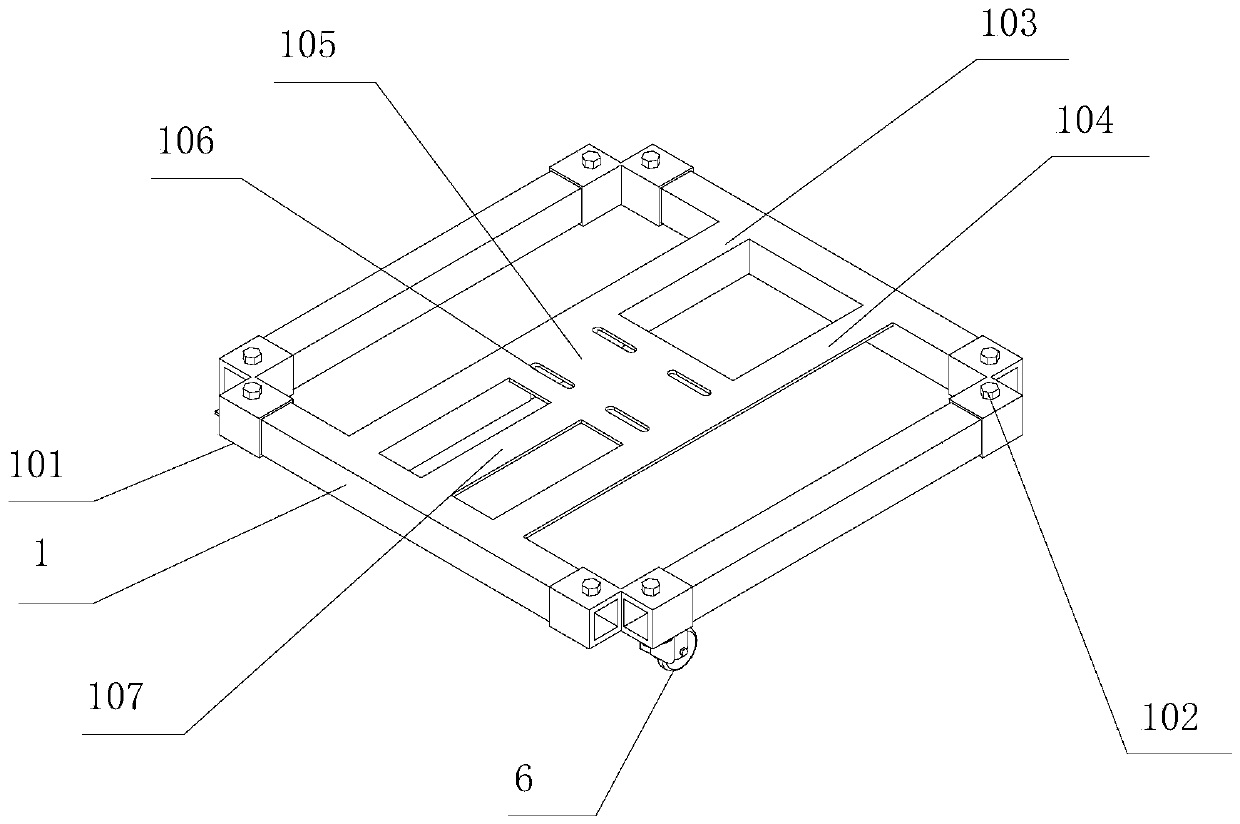
[0031] like Figure 1-7 As shown, the present invention includes a chassis, a column 3, an output steel rope I501 and a hoisting motor, and the chassis includes four square tubes 1 connected end-to-end, and the four square tubes 1 can be integrally formed or welded. , In order to facilitate production, the present invention preferably adopts welding connection, and four square tubes 1 with the same structure and size are welded to each other to reduce production cost. , the four corners of the four square tubes 1 are all convenient to set the extended support rod 2, which simplifies the installation difficulty of the extended support rod 2. The end of the square tube 1 is sleeved with the extended support rod 2, and the cross-sectional shape of the extended support rod 2 is The shape of the inner cavity of the square tube 1 is consistent; in order to facilitate the extension of the support rod 2 and the sleeve of the square tube 1, the extension support rod 2 and the square tube


PUM


Abstract

The invention belongs to a lifting machine, and particularly relates to a multifunctional sunlight room installation lifting machine. The multifunctional sunlight room installation lifting machine comprises a bottom frame, a lifting motor and a first output steel rope; the bottom frame comprises four square pipes which are connected end to end, lengthened supporting rods sleeve the end of the square pipe, universal wheels are arranged at the bottoms of the square pipes and the lengthened supporting rods, fastening screws are arranged at the ends of the square pipes, a stand column installing platform is arranged between the two opposite square pipes, the stand columns are arranged on the stand column installing platform, telescopic rods are arranged on the stand columns, fixed pulleys arefixedly arranged on the telescopic rods, the lifting motor is arranged on the bottom frame, and the first output steel rope of the lifting motor is arranged around the fixed pulley. According to the lifting machine, the weight is large, the stability is good, the application range is wide, and the assembly is convenient and flexible.

Description


Claims


Application Information

Patent Timeline
Owner 何齐
Why Eureka
Try Eureka