Automatic ejector pin spiral groove grinding device

A technology of grinding device and spiral groove, which is applied in the direction of tangent device, large fixed member, tangent machine, etc., can solve the problems of high cost of alloy tools, high cost of machine tools, time required, etc., to achieve low cost, improve production efficiency, clamping fast effect

Pending Publication Date: 2019-10-22
广州市艺强电器有限公司
View PDF0 Cites 0 Cited by
  • Summary
  • Abstract
  • Description
  • Claims
  • Application Information

AI Technical Summary

Benefits of technology

The technical effect of this patented method described by the inventor overcomes previous methods that were expensive or difficult for users who needed it themselves. It allows for accurate and consistently placed spirals without requiring external tools like screwdrivers or other equipment. This makes manufacturing faster while reducing costs associated therewith compared to traditional ways such as machining.

Problems solved by technology

This patented technical problem addressed in this patents relates to improving the speed at which manufacturing processes involve creation or modification of metal shapes during production. Specifically, there has been a long felt need for improved methods of producing these types of metals quickly without requiring expensive tools like mills or screwdrivers. Additionally, current techniques require skilled workers manually supporting the workpiece while performing various steps, resulting in less efficient use of resources than desired.

Method used


Image

  • Automatic ejector pin spiral groove grinding device
  • Automatic ejector pin spiral groove grinding device
  • Automatic ejector pin spiral groove grinding device

Examples


Embodiment Construction

[0024] The present invention will be further described below in conjunction with accompanying drawing and specific embodiment:

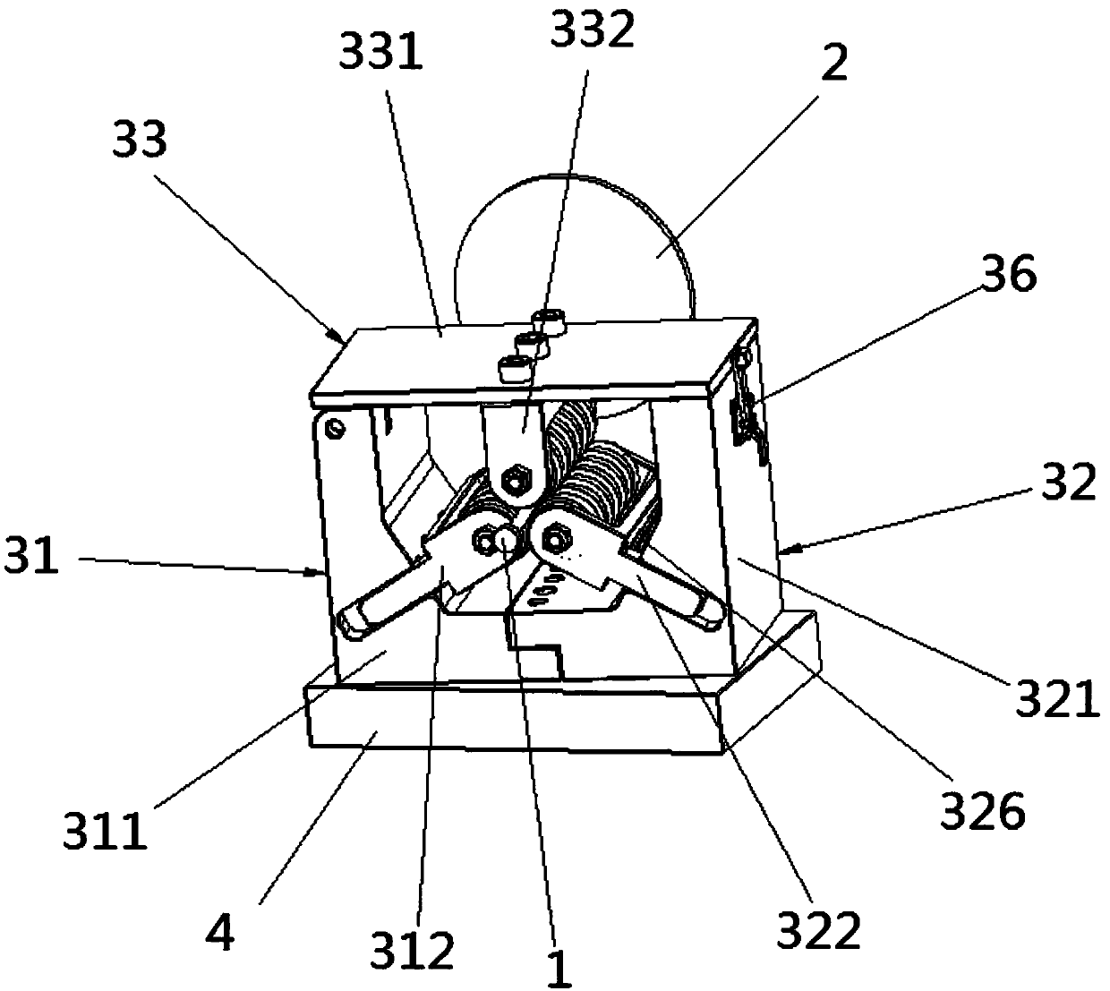
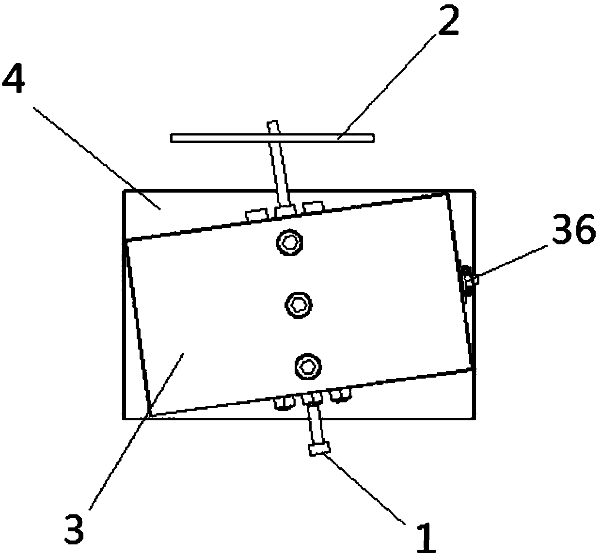
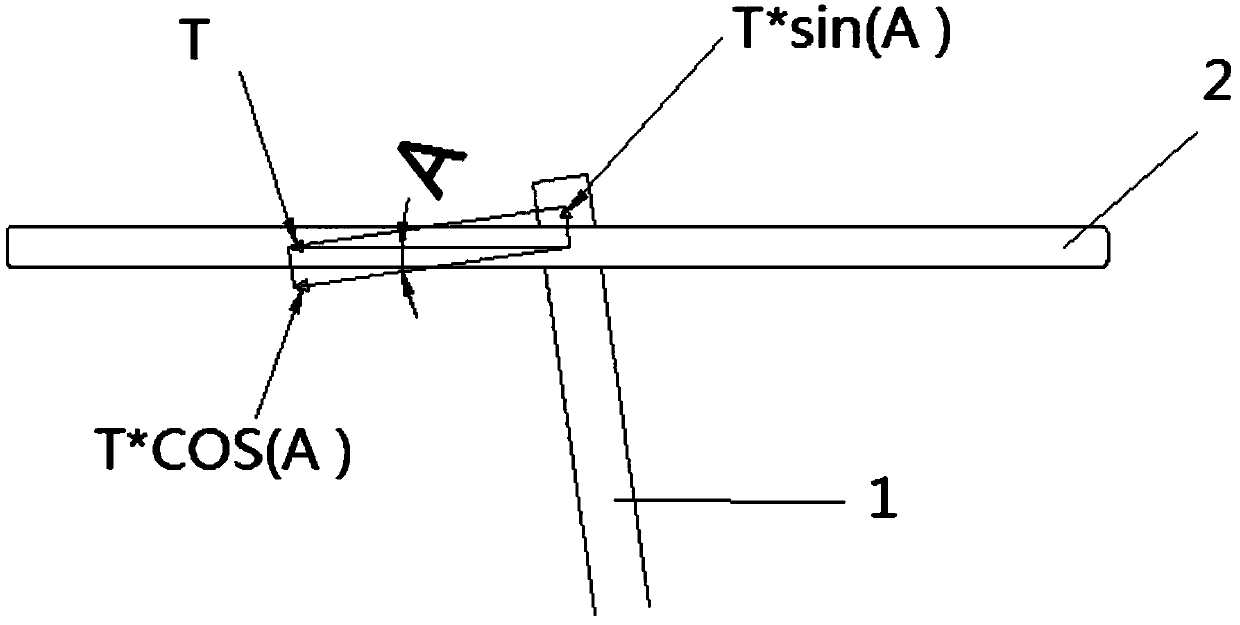
[0025] Such as Figure 1-2 As shown, the thimble spiral groove automatic grinding device of the present invention includes a cutting wheel 2 and a mounting seat 3 arranged in front of the cutting wheel 2 . Because the cutting wheel 2 only rotates clockwise and has no forward movement, and the thimble 1 needs to move in two directions to realize the processing of the spiral groove, that is, the rotational movement plus the forward movement. In order to give this forward force, it is necessary to place the thimble 1 at an angle A, such as image 3 As shown, the force T on the thimble 1 received by the cutting wheel 2 is counterclockwise. According to the decomposition of the force, two forces can be decomposed: the force T*sin(A) in the forward direction and the force T*cos in the counterclockwise direction. (A), so that the thimble 1 moves in these two


PUM

PropertyMeasurementUnit
Diameteraaaaaaaaaa
Outer diameteraaaaaaaaaa

Abstract

The invention relates to the field of hardware dies, in particular to an automatic ejector pin spiral groove grinding device. The automatic ejector pin spiral groove grinding device mainly comprises acutting wheel and an installing base arranged in front of the cutting wheel. The installing base and the cutting wheel deflect by a certain angle to be arranged. The installing base comprises a leftclamping part, a right clamping part and an upper clamping part jointly clamping an ejector pin, and the surface of the tail of the ejector pin is right opposite to the bottom of the cutting wheel forcutting. The automatic ejector pin spiral groove grinding device is low in cost, an ejector pin spiral groove can be machined on an ordinary grinding machine, positioning is accurate and stable, clamping is rapid, person hand slight holding is not needed in the machining process, automation is completely achieved, the production efficiency is greatly improved, and the time and labor cost is saved.

Description


Claims


Application Information

Patent Timeline
Owner 广州市艺强电器有限公司
Why Eureka
Try Eureka