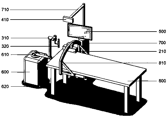
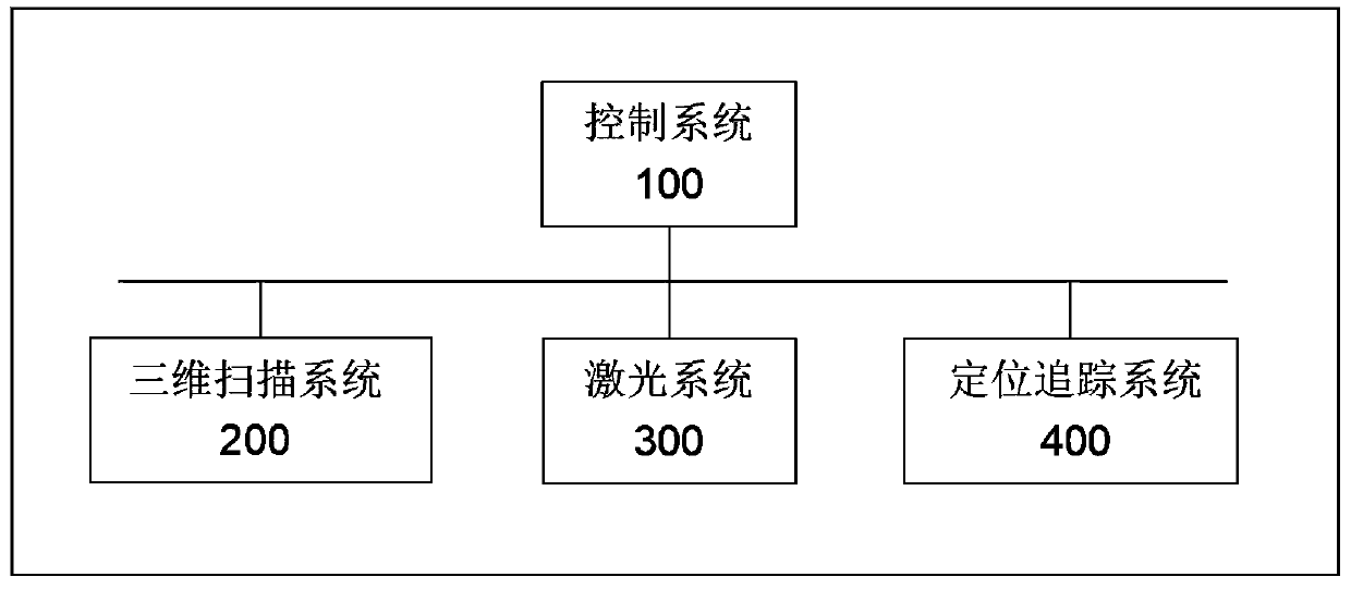
Automatic laser treatment robot
A technology of laser therapy and robotics, applied in the field of medical equipment, can solve the problems of labor-intensive and labor-saving, and achieve the effect of saving labor
- Summary
- Abstract
- Description
- Claims
- Application Information
AI Technical Summary
Benefits of technology
Problems solved by technology
Method used
Image

Examples
Embodiment Construction
[0024] The implementation of the present application will be described by specific specific examples below, and those skilled in the art can easily understand other advantages and effects of the present application from the content disclosed in this specification.
[0025] It should be noted that in this application, up, down, left and right in the figure are regarded as up, down, left and right of the automatic laser therapy robot described in this specification.
[0026] Exemplary embodiments of the present application will now be described with reference to the accompanying drawings; however, the present application may be implemented in many different forms and are not limited to the embodiments described herein, which are provided for the purpose of exhaustively and completely disclosing the present invention. application and fully convey the scope of the application to those skilled in the art. The terms used in the exemplary embodiments shown in the drawings are not limita
PUM
 Abstract
Description
Claims
Application Information
 - R&D Engineer
- R&D Manager
- IP Professional
- Industry Leading Data Capabilities
- Powerful AI technology
- Patent DNA Extraction
Browse by: Latest US Patents, China's latest patents, Technical Efficacy Thesaurus, Application Domain, Technology Topic.
© 2024 PatSnap. All rights reserved.Legal|Privacy policy|Modern Slavery Act Transparency Statement|Sitemap