Gradient magnetic field generator
A gradient magnetic field, generator technology, applied in the direction of motors, electric vehicles, electrical components, etc., can solve problems such as the inability to perform continuous work
- Summary
- Abstract
- Description
- Claims
- Application Information
AI Technical Summary
Problems solved by technology
Method used
Image


Examples
Embodiment approach 1
[0020] by figure 1 , figure 2 , image 3 An example is as follows:
[0021] The design scheme of the gradient magnetic field is as follows: the permanent magnets ⑧ are distributed at equal angles along the radial direction of the permanent magnet frame ①, and are set at equal distances along the radial direction. Taking the illustration as an example (but not limited to this design) a total of 36 permanent magnets ⑧ are arranged, and the angles are evenly distributed (360 / 36) 10 degrees. The total deviation distance between the first permanent magnet 1 and the last permanent magnet 36 can be calculated according to According to the actual situation (such as the size of the permanent magnet, the magnetic properties of the permanent magnet, the size of the permanent magnet frame, the diameter of the roller, the weight of the roller, the material of the roller, etc.) to set. The deviation distance of each adjacent permanent magnet=total deviation distance / total number of per
Embodiment approach 2
[0032] by Figure 4 , Figure 5 An example is as follows:
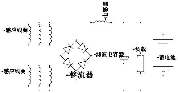
[0033] The gradient magnetic field, roller ②, micro switch ⑥ and other settings are similar to the first embodiment, but the induction coil Set on the outer cylindrical surface of the roller ②, on the induction coil frame Radial induction coil with at least one roller ② inside The induction coil will be cut when the roller rolls along the outer cylinder of the permanent magnet frame ① and in the closed induction coil Internally generate potential and current, which can drive electrical appliances after rectification and filtering, and can also charge batteries.
[0034] Implementation of case three:
[0035] by Image 6 An example is as follows:
[0036] Gradient magnetic field, roller ②, induction coil Etc. is the same as Embodiment 1, and the difference from Embodiment 2 is that the roller ② and the permanent magnet ③ with built-in roller ② need more than 2 groups, and the magnetic isolation sheet Accor
Embodiment approach 5
[0043] by Figure 8 As explained below:
[0044] Compared with the previous embodiments one to four, the biggest difference of embodiment five is that the roller ③ rolls along the inner cylindrical surface of the permanent magnet frame ①, and the layout of the permanent magnets makes the magnetic balance point on the 180 horizontal line.
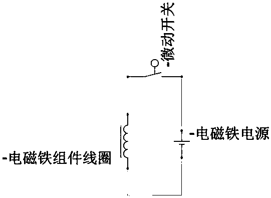
[0045] Considering that the permanent magnets are densely arranged at the magnetic balance point, there is no space for the ejector head to be arranged (of course, the ejector head can be designed by perforating the permanent magnet 36 or 35, but the process is more complicated), and a ejector fork ⑤ has been designed. When the roller ③ rolls from the position of the permanent magnet 35 to the permanent magnet 36 under the action of the gradient magnetic field, the edge of the roller ③ compresses the ejector rod fork ⑤, and then triggers the micro switch ④ to connect the coil of the electromagnet assembly ⑥, and the electromagnet attracts the e
PUM
 Abstract
Description
Claims
Application Information
 - R&D Engineer
- R&D Manager
- IP Professional
- Industry Leading Data Capabilities
- Powerful AI technology
- Patent DNA Extraction
Browse by: Latest US Patents, China's latest patents, Technical Efficacy Thesaurus, Application Domain, Technology Topic.
© 2024 PatSnap. All rights reserved.Legal|Privacy policy|Modern Slavery Act Transparency Statement|Sitemap