Method for forming acrylonitrile rubber drop beads on antislip gloves

A molding method and nitrile rubber technology are applied to gloves, devices for coating liquid on the surface, clothing, etc., to achieve the effect of easy operation and overcoming easy peeling

Inactive Publication Date: 2011-08-17
陈国平
View PDF4 Cites 1 Cited by
  • Summary
  • Abstract
  • Description
  • Claims
  • Application Information

AI Technical Summary

Benefits of technology

This patented technology uses special types of rubbers that are made from water instead of traditional chemicals like acrylic acid or methylmorpholine sulfone (MMS). These rubers have better resistance against damage caused by external factors but they don't work well when used with other substances due to their tendency towards being dissolved away during use. They also provide longer lifespan compared to current methods for creating these items.

Problems solved by technology

The technical problem addressed in this patented text relates to reducing slippage between rubbery surfaces when wearing conventional grips made from these types of materials due to their low surface energy level compared with other alternatives like plastic or metal.

Method used


Image

  • Method for forming acrylonitrile rubber drop beads on antislip gloves
  • Method for forming acrylonitrile rubber drop beads on antislip gloves

Examples


Embodiment Construction

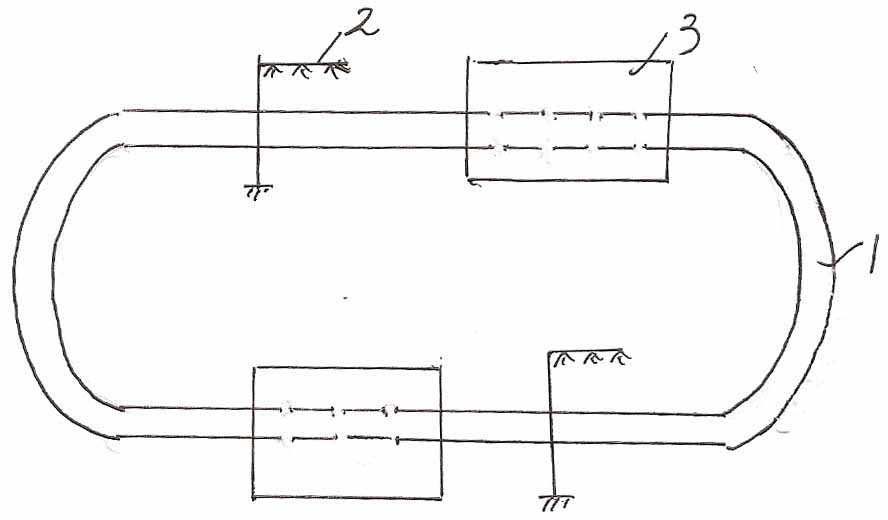
[0013] A kind of nitrile rubber bead molding method of non-slip gloves, comprises the following steps:

[0014] (1) The nitrile rubber bead injection device is arranged above the glove conveyor belt 1. When the glove passes through the nitrile rubber bead injection device 2, the nitrile rubber bead injection device injects the nitrile rubber bead on the glove. Nitrile beads form on gloves;

[0015] (2) The gloves injected with beads are sent to the oven 3 for drying treatment through the glove conveyor belt, and the temperature of the oven is 100~110°C;

[0016] The glove conveyor is in the shape of an oval loop and passes through the oven.

[0017] Nitrile bead injection unit can be installed above multiple stations on the glove conveyor belt.


PUM


Abstract

The invention discloses a method for forming acrylonitrile rubber drop beads on antislip gloves, which comprises: arranging an acrylonitrile rubber drop bead injecting device above a glove conveyor belt, so that the acrylonitrile rubber drop bead injecting device can inject acrylonitrile rubber drop beads on the antislip gloves when the gloves pass by the acrylonitrile rubber drop bead injecting device to form acrylonitrile rubber beads on the gloves; and feeding the gloves subjected to drop bead injection into an oven through the conveyor belt for drying, wherein the temperature of the oven is 100 to 110 DEG C, and the glove conveyor belt is shaped like an elliptical ring and passes through the oven. In the invention, the acrylonitrile rubber, which is an aqueous material, is used as a drop bead material, so the method meets requirement for environment protection. The method can realize continuous operation and convenient manipulation, and overcome the drawbacks such as peeling of the aqueous material.

Description


Claims


Application Information

Patent Timeline
Owner 陈国平
Why Eureka
Try Eureka