Servo system rotation clearance simulation device

A simulation device and servo system technology, applied in rigid shaft couplings, mechanical equipment, couplings, etc., can solve the problems of requirements, experimental data not accurate and comprehensive, and high experimental conditions, and achieve low cost, simple structure, and abundant Effect of Experimental Conditions

Pending Publication Date: 2019-12-13
BEIJING QTCREATE TECH
View PDF0 Cites 0 Cited by
  • Summary
  • Abstract
  • Description
  • Claims
  • Application Information

AI Technical Summary

Problems solved by technology

The experimental data obtained are either not accurate and comprehens

Method used


Image

  • Servo system rotation clearance simulation device

Examples


Embodiment Construction

[0028] The present invention will be further described in detail below in conjunction with the accompanying drawings.

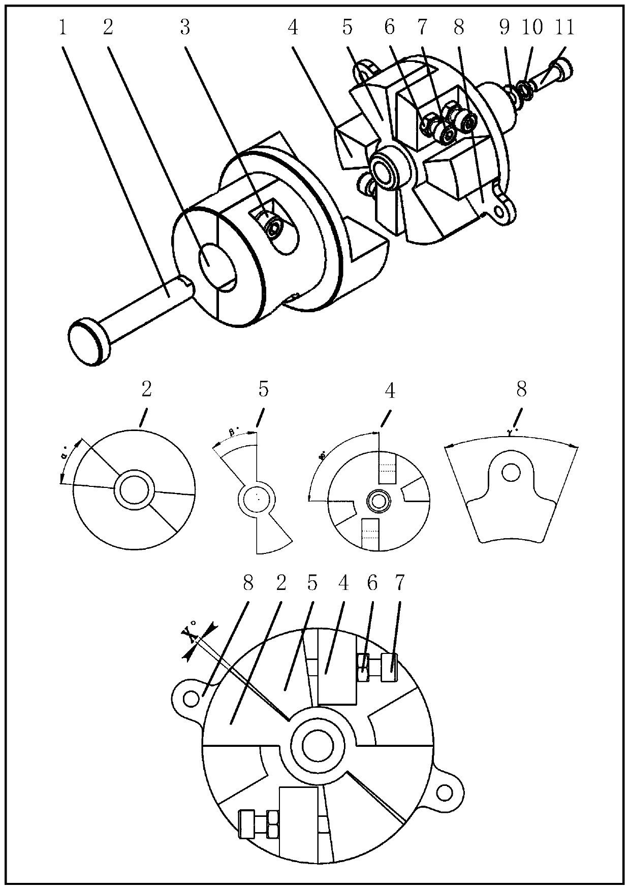
[0029] The invention relates to a servo system rotation gap simulation device, which is a simulation device specially used for studying the nonlinear effect of the servo system rotation gap. See figure 1 As shown, it includes coaxial fixed rod 1, roulette coupling 2, coupling fastening screw 3, fixed-angle roulette 4, rotary slider 5, lock nut 6, adjusting screw 7, fixed-angle plug Ruler 8, coaxial spacer 9, spring spacer 10 and fastening screw 11; Their mutual positional relationship is: wheel coupling 2, rotary slider 5 and fixed-angle wheel 4 are arranged in order, and the rotation The slider 5 is in the middle; the coaxial fixed rod 1 passes through the round hole in the middle of the wheel coupling 2 and the fixed-angle wheel 4, and is connected with the coaxial spacer 9, the spring spacer 10 and the fastening screw 11 through threads Fix together; the co


PUM


Abstract

The invention provides a servo system rotation clearance simulation device which comprises a coaxial fixing rod, a wheel disc coupling, a coupling fastening screw, a fixed-angle wheel disc, a rotary sliding block, locking nuts, adjusting screws, a fixed-angle feeler gauge, a coaxial washer, a spring washer and a fastening screw. The wheel disc coupling, the rotary sliding block and fixed-angle wheel disc are arranged in order with the rotary sliding block in the middle. The coaxial fixing rod penetrates through a round hole in the middle of the wheel disc coupling and a round hole in the middle of the fixed-angle wheel disc and is fixed to the coaxial washer, the spring washer and the fastening screw through threaded connection. The coupling fastening screw is installed on the wheel disc coupling, the locking nuts and the adjusting screws are installed on the fixed-angle wheel disc, and the fixed-angle feeler gauge is inserted into a position space of the fixed-angle wheel disc. The servo system rotation clearance simulation device is simple in structure, convenient to install and low in cost, and has the value of promotion and application.

Description


Claims


Application Information

Patent Timeline
Owner BEIJING QTCREATE TECH
Why Eureka
Try Eureka