Oil fume purifying equipment and oil fume purifying method thereof

A technology for oil fume purification and oil fume, which is applied in chemical instruments and methods, oil fume removal, separation methods, etc., can solve the problems of waste of cooktop space, inconvenient collection and cleaning, beautiful images, etc., and achieves increased space, simple structure, and easy miniaturization. the effect of

Pending Publication Date: 2019-12-24
张黎明
View PDF0 Cites 0 Cited by
  • Summary
  • Abstract
  • Description
  • Claims
  • Application Information

AI Technical Summary

Problems solved by technology

However, if the oil fume purification treatment device is independent of the oil fume extraction device, the overall volume of the range hood will be larger, and the image will be beautiful if it is placed alone
In addition, the traditional cooker hood is separated from the cooker, which also wastes the space under the cooker, and cannot make full use of the overall space of the cooker and range hood
[0005] In addition, the traditional range hood extracts the oil fume upwards, but the oil fume will inevitably condense into droplets during the extraction process, and the oil droplets will slide down under the action of gravity, which is not easy to collect and clean
In this way, the oil droplets produced by the fume gas will be scattered everywhere in the range hood, and long-term storage will also cause poor sanitation.

Method used


Image

  • Oil fume purifying equipment and oil fume purifying method thereof
  • Oil fume purifying equipment and oil fume purifying method thereof
  • Oil fume purifying equipment and oil fume purifying method thereof

Examples


Example Embodiment

[0082] The following description is used to disclose the present invention so that those skilled in the art can implement the present invention. The preferred embodiments in the following description are only examples, and those skilled in the art can think of other obvious variations. The basic principles of the present invention defined in the following description can be applied to other embodiments, modifications, improvements, equivalents, and other technical solutions that do not depart from the spirit and scope of the present invention.

[0083] Those skilled in the art should understand that, in the disclosure of the present invention, the terms "longitudinal", "lateral", "upper", "lower", "front", "rear", "left", "right", " The orientation or positional relationship indicated by "vertical", "horizontal", "top", "bottom", "inner", "outer", etc. are based on the orientation or positional relationship shown in the drawings, which is only for the convenience of describing the p


PUM


Abstract

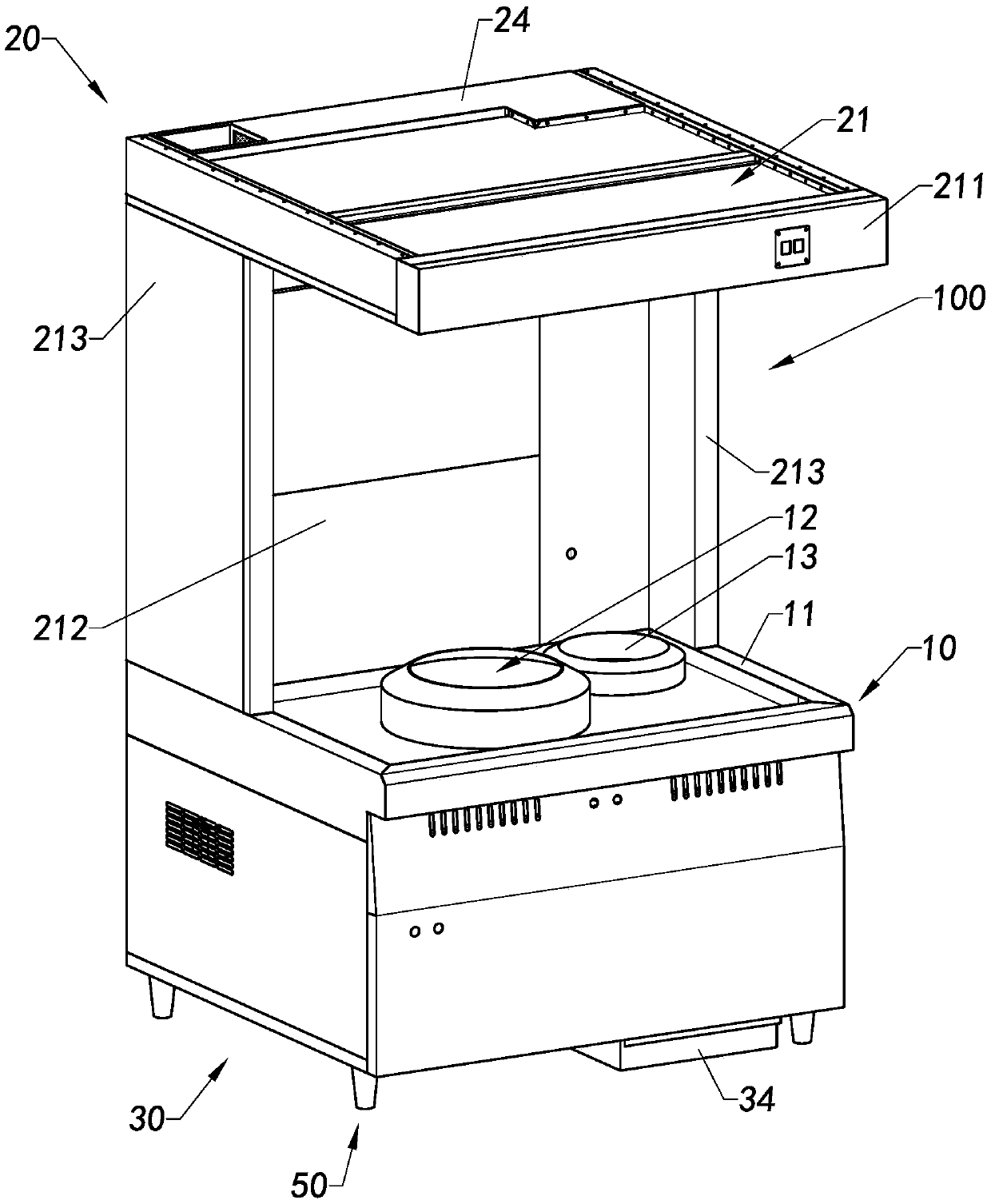
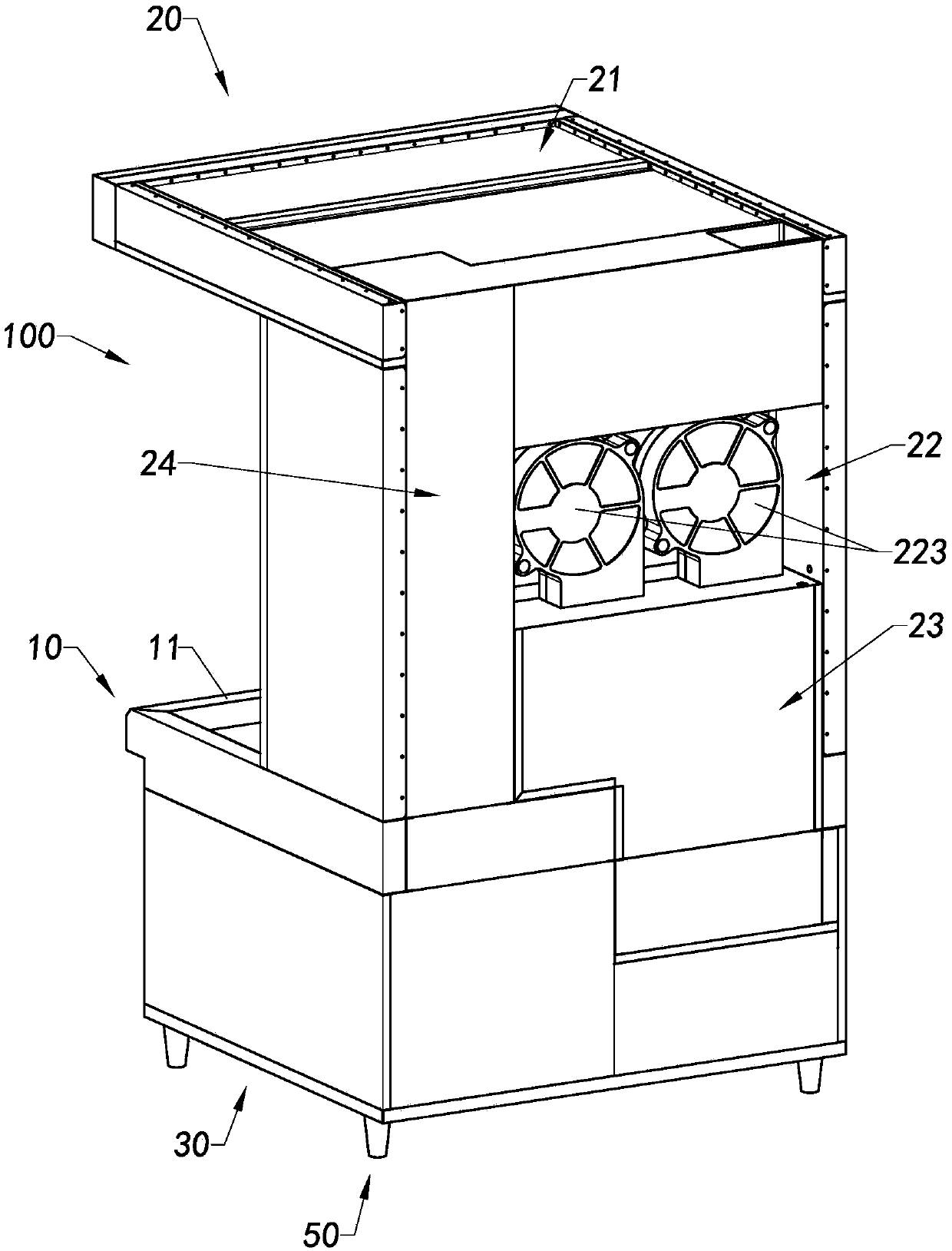
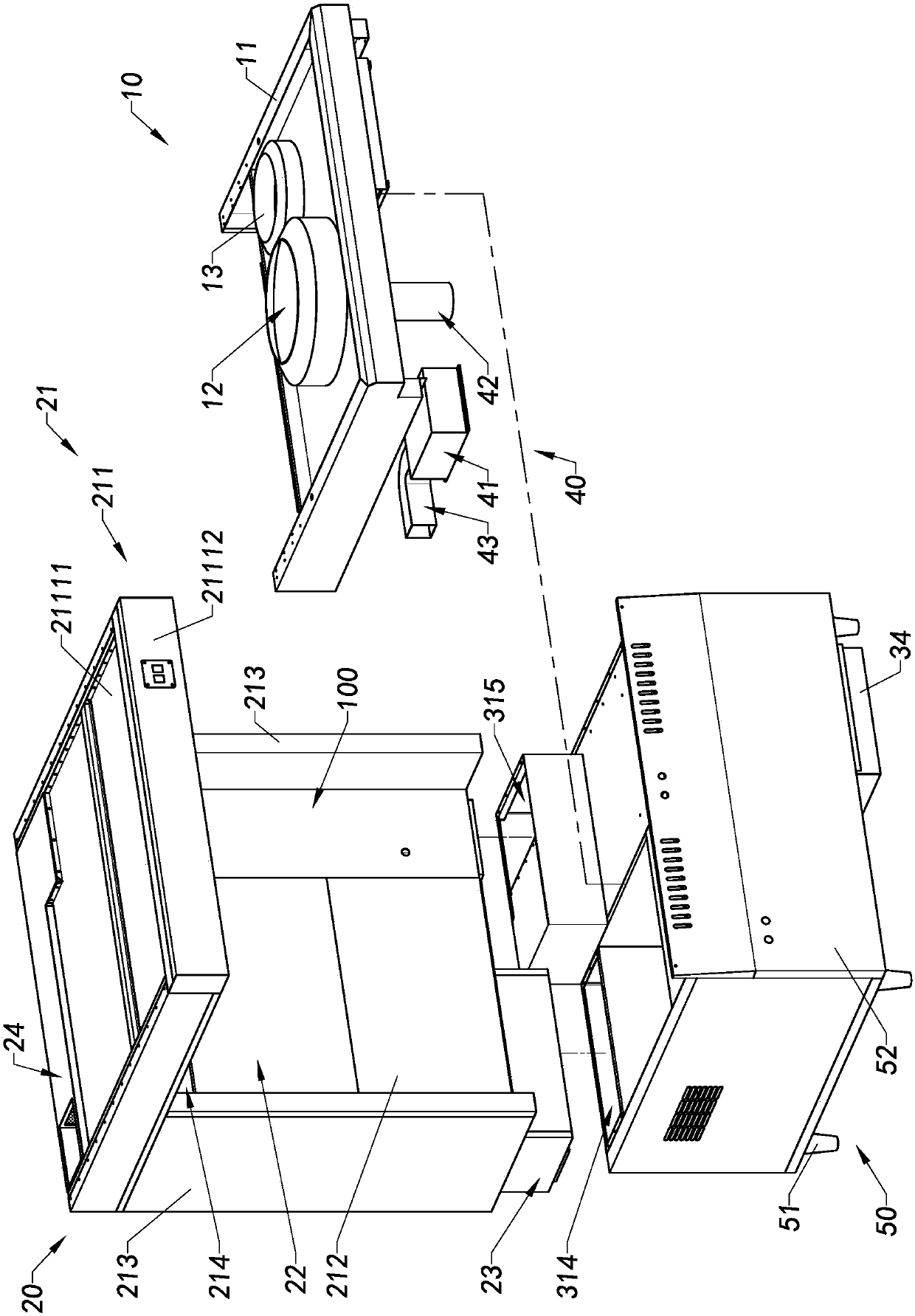
The invention provides oil fume purifying equipment and an oil fume purifying method thereof. The oil fume purifying equipment comprises an operating table, an oil fume collecting device and an oil fume purifying device. The oil fume collecting device is kept above the operation table, the oil fume collecting device collects oil fume gas and exhausts purified gas, the oil fume purifying device communicates with the oil fume collecting device, the oil fume purifying device receives the oil fume gas collected by the oil fume collecting device, and the oil fume purifying device is used for separating and extracting oil drops in the oil fume gas and guiding the purified gas upwards to the oil fume collecting device.

Description


Claims


Application Information

Patent Timeline
Owner 张黎明
Why Eureka
Try Eureka