Road deicing and snow removing machine

A technology for snow blowers and highways, which is used in snow surface cleaning, construction, cleaning methods, etc., can solve the problems of slow deicing speed, slippage, and small size of deicing devices, and achieves the effect of increasing the effective area and saving power output.

Pending Publication Date: 2020-03-24
曹玉财
View PDF3 Cites 0 Cited by
  • Summary
  • Abstract
  • Description
  • Claims
  • Application Information

AI Technical Summary

Benefits of technology

This patented technology allows for easy installation of ice-changing devices within boxes or containers without causing damage during use. These systems include ice breaking tools with limited lifespan due to high impacts caused when they hit hard objects such as rocks or stones. They also allow for efficient removal of snow and debris from indoor surfaces while maintaining their safe distance between them. Additionally, these machines help remove larger items like plugs made up mostly of rubber material called frost bags which may be harmful if left untreated overtime. Overall, this system improves efficiency and reduces maintenance costs compared to existing methods.

Problems solved by technology

This patented technical problem addressed in this patents relates to finding better ways to prevent or reduce damage caused from frozen roads due to accumulation of water (ice) along their edges). Current methods involve manually removing these layers, causing them to lose weight overtime. There is currently no efficient way to efficiently remove these layers before they get stuck together again.

Method used


Image

  • Road deicing and snow removing machine
  • Road deicing and snow removing machine
  • Road deicing and snow removing machine

Examples


Embodiment

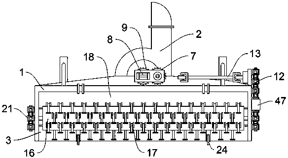
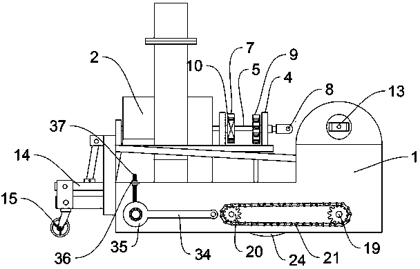
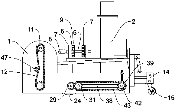
[0027] Embodiment: according to specification Figure 1-6 And 8, it can be seen that, in use, the deicing device is connected on the dragged car body, and the connecting rod 8 and the power shaft 13 are connected with the gearbox on the car body, and the power shaft 13 is connected to the gearbox by the front end universal joint. The horizontal axis is connected, and the connecting rod 8 is connected with the longitudinal axis through the front universal joint (instruction attached Figure 8 ), at this time the deicing device moves, the connecting rod 8 rotates, and makes the third gear 9 rotate, and because the third gear 9 meshes with the first gear 6, the first shaft 5 on the first gear 6 rotates , the second gear 7 rotates at the same time, because the second gear 7 is meshed with the fourth gear 10, so that the fourth gear 10 rotates. The transmission rod 44 drives the ice-discharging blade 46 to rotate, and the power shaft 13 rotates, so that a pair of power gears 11 rotat


PUM


Abstract

The invention discloses a road deicing and snow removing machine, relating to the field of pavement deicing. The machine comprises a box body, an ice discharging box is mounted on the box body; an icedischarging device is mounted in the ice discharging box; an ice chiseling cavity, a deicing cavity and a cleaning cavity are formed in the box body, and ice chiseling devices are installed in the ice chiseling cavity, the deicing cavity and the cleaning cavity correspondingly. The ice chiseling device is arranged in the box body, so that ice in the box body is chiseled and crushed by the ice chiseling hammer; a certain safety height is formed between the ice chiseling hammer and the ground through the limiting device, the inside is prevented from being damaged by the ice chiseling hammer; large ice blocks can be conveyed into the ice discharging device through the ice removing device; the cleaning device can be used for conveying small and residual crushed ice into the ice discharging device; the ice discharging device is used for discharging crushed ice and large-block ice out of the box body, rotating rods on the two sides of the cleaning device can adjust the sweeping height underthe action of a threaded sleeve and a threaded rod, then the effective sweeping area is increased, and a cleaning brush in the cleaning device is prevented from damaging the ground.

Description


Claims


Application Information

Patent Timeline
Owner 曹玉财
Why Eureka
Try Eureka