Electric waterproof structure of air outlet of humidifier and control method

A waterproof structure and control method technology, applied in heating and ventilation control systems, heating methods, air humidification systems, etc., can solve problems affecting user experience, damage to humidifier electrical components, safety accidents, etc., and achieve the effect of improving user experience

Pending Publication Date: 2020-03-31
FOSHAN SHUNDE DEERMA ELECTRIC APPLIANCES CO LTD
View PDF0 Cites 0 Cited by
  • Summary
  • Abstract
  • Description
  • Claims
  • Application Information

AI Technical Summary

Benefits of technology

This patented technology describes different ways to connect two parts together by moving them apart easily while maintaining their original function. One way involves connecting both parts tightly together instead of just one part being fixed. Another approach uses sensors like switches to detect if there are any leaks inside the system. By doing this, the device becomes more reliable because they only require electrical connections rather than physical ones.

Problems solved by technology

There currently exist various technical solutions aimed towards solving issues related to moisture evaporation caused by condensation within indoor environments such as those described earlier. These include reducing the buildup of debris around the device itself while maintaining proper performance levels (humidity) and minimizing damage to electronic devices like sensors and motors. However, current methods require frequent maintenance and replacement of these parts leading to increased costs associated therewith.

Method used


Image

  • Electric waterproof structure of air outlet of humidifier and control method
  • Electric waterproof structure of air outlet of humidifier and control method
  • Electric waterproof structure of air outlet of humidifier and control method

Examples


Embodiment Construction

[0045] The electric waterproof structure of the air outlet of the humidifier and the control method thereof of the present invention are described in conjunction with the accompanying drawings.

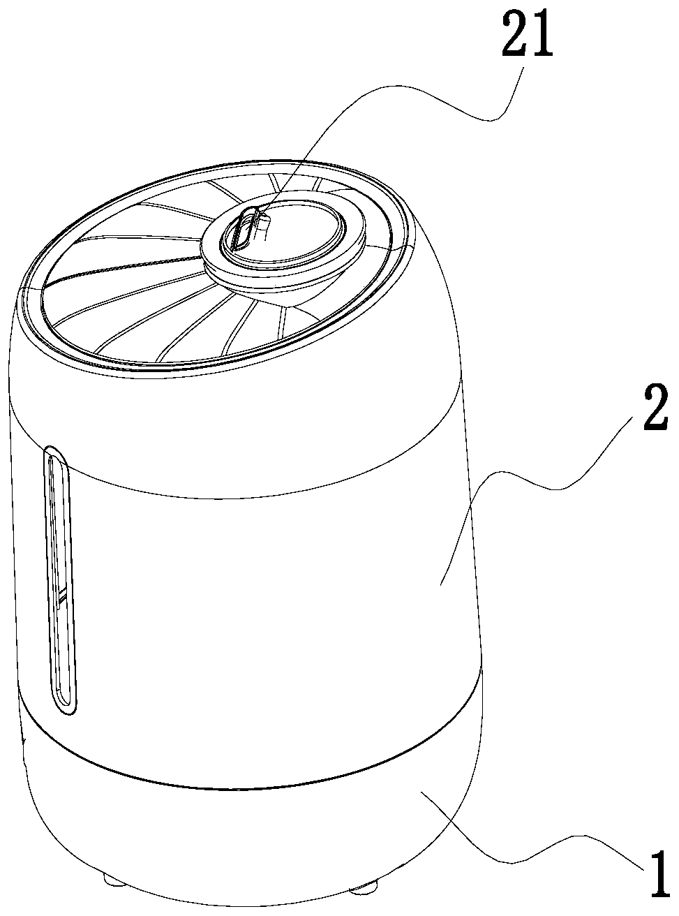
[0046] Such as figure 1 As shown, the humidifier of the present invention includes a base 1 and a water tank 2 , the base 1 and the water tank 2 are detachably connected, and the bottom of the water tank 2 is provided with a mist outlet 21 .

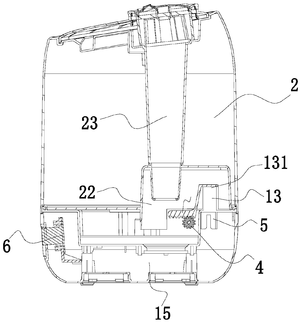
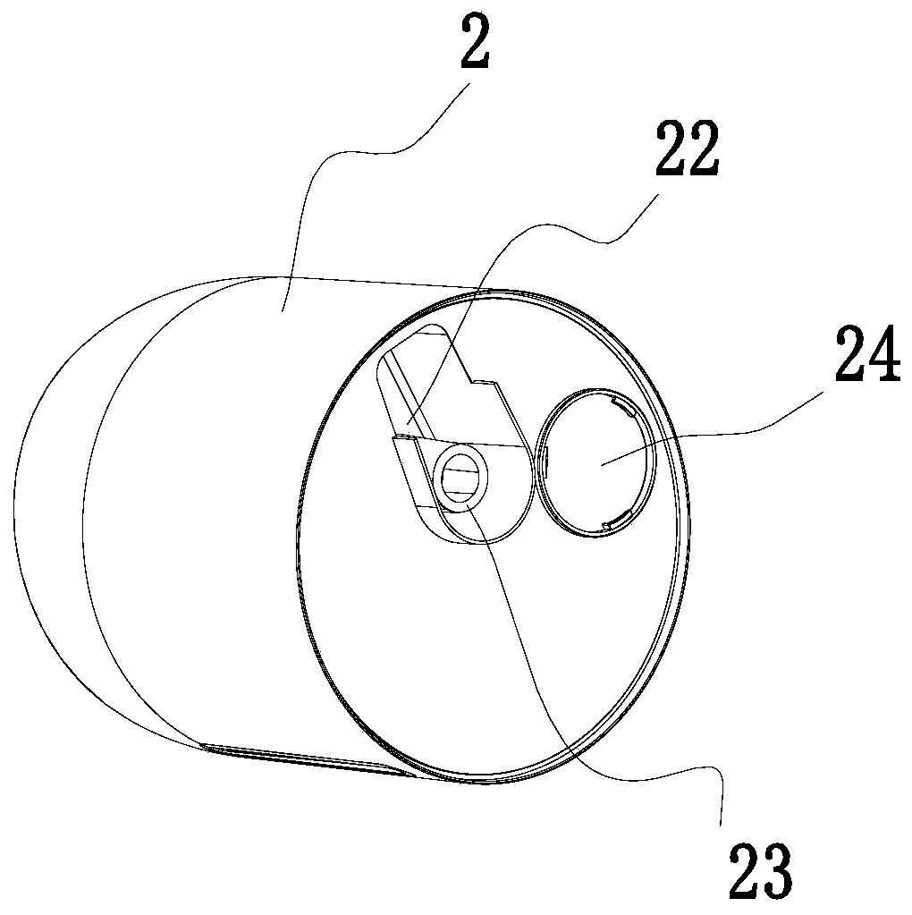
[0047] Such as Figure 2-5 As shown, the base 1 is provided with a fan 5, the top of the base 1 is provided with a partition 11, the partition is provided with an air outlet pipe 13, and the top of the air outlet pipe 13 is provided with an air outlet 131, so The air outlet pipe 13 is arranged through the partition plate 11, and the fan 5 is located below the air outlet pipe 13, so that the air outlet of the fan 5 communicates with the air outlet pipe 13; A control circuit board 6 is provided, and the control circuit board 6 is electrically conne


PUM


Abstract

The invention discloses an electric waterproof structure of an air outlet of a humidifier, which comprises a base and a fan, wherein the fan is arranged in the base; the base is provided with an air outlet pipe, the air outlet pipe is communicated with an air blowing opening of the fan, and the air outlet pipe is provided with an air outlet; the top of the air outlet is connected with a sliding block, and the bottom of the sliding block penetrates through the base and is arranged in the base; the base is internally provided with a driving motor, a driving shaft of the driving motor is sleevedwith a driving gear, and the bottom of the sliding block is provided with a rack meshed with the driving gear; the base is internally provided with a control circuit board, and the control circuit board is electrically connected with the driving motor and the fan. The invention further provides a control method. According to the electric waterproof structure of the air outlet of the humidifier andthe control method, the air outlet structure of the humidifier is improved to be automatically opened and closed, so that the air outlet is in a closed state after the humidifier stops being used andwhen the humidifier is cleaned.

Description


Claims


Application Information

Patent Timeline
Owner FOSHAN SHUNDE DEERMA ELECTRIC APPLIANCES CO LTD
Why Eureka
Try Eureka