Novel mechanical-hydraulic control triaxial creep testing machine

A three-axis creep and testing machine technology, applied in the field of creep testing machines, can solve the problems of inconvenient replacement of the upper force column and the force transmission column sleeve, large loading error, and influence on the test effect, etc., and achieve good comprehensive performance, The test piece is easy to install and the overall structure is compact

Pending Publication Date: 2020-04-17
CHENGDU SIFU HYDRAULIC EQUIP CO LTD
View PDF0 Cites 0 Cited by
  • Summary
  • Abstract
  • Description
  • Claims
  • Application Information

AI Technical Summary

Benefits of technology

This innovation improves upon existing devices by making them smaller while still maintaining their strength properties. It also makes it easier to install different types of tests without affecting its function or quality level. Overall, this technology allows researchers to perform more accurate measurements over time than previously possible due to reduced size and improved structural integrity compared to previous designs.

Problems solved by technology

This patents describes three technical features for achieving accurate tests: 1) avoidance of discomfort or difficulty with changing dimensions due to limitations such as tightening presses; 2) ensuring consistently good results despite changes in dimensionality without causing damage from excessive stress loads over longer periods of time; 3) reducing the risk of contamination while maintaining effective performance under various conditions.

Method used


Image

  • Novel mechanical-hydraulic control triaxial creep testing machine

Examples


Embodiment Construction

[0025] Embodiments of the technical solutions of the present invention will be described in detail below in conjunction with the accompanying drawings. The following examples are only used to illustrate the technical solutions of the present invention more clearly, and therefore are only examples, rather than limiting the protection scope of the present invention.

[0026] It should be noted that, unless otherwise specified, the technical terms or scientific terms used in this application shall have the usual meanings understood by those skilled in the art to which the present invention belongs.

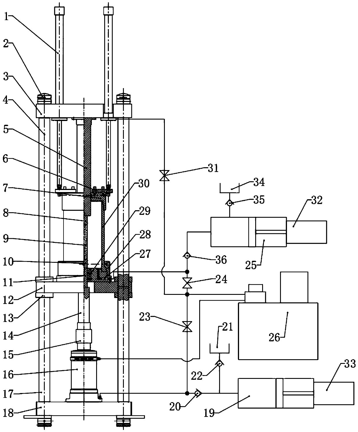
[0027] Such as figure 1 As shown, a new three-axis creep testing machine controlled by mechanical fluid includes an upper bearing plate 3, a middle plate 12 and a lower bearing plate 18; An upper column 4, the two ends of a plurality of the upper columns 4 are respectively connected to the edge of the upper bearing plate 3 and the edge of the middle plate 12; a plurality of lower colum


PUM


Abstract

The invention discloses a novel mechanical-hydraulic control triaxial creep testing machine, which comprises an upper force bearing plate, a middle plate and a lower force bearing plate, wherein a plurality of upper stand columns are arranged between the upper force bearing plate and the middle plate, and the two ends of each upper stand column are connected with the edge of the upper force bearing plate and the edge of the middle plate respectively; a plurality of lower stand columns are arranged between the middle plate and the lower force bearing plate, and the two ends of each lower standcolumn are connected with the edge of the middle plate and the edge of the lower force bearing plate respectively; a pressure chamber base is fixedly connected to the middle of the upper surface of the middle plate, a pressure chamber end cover is arranged above the pressure chamber base, a pressure chamber cylinder is arranged between the pressure chamber base and the pressure chamber end cover,and the pressure chamber base, the pressure chamber end cover and the pressure chamber cylinder form closed space; an axial oil cylinder is fixedly arranged on the lower force bearing plate, a push rod of the axial oil cylinder is vertically upward and connected with a lower force transmission column, the lower end of the lower force transmission column is connected with the push rod of the axialoil cylinder, and the upper end of the lower force transmission column extends upwards and sequentially penetrates through the middle plate and the pressure chamber base.

Description


Claims


Application Information

Patent Timeline
Owner CHENGDU SIFU HYDRAULIC EQUIP CO LTD
Why Eureka
Try Eureka