Multifunctional electron beam zone melting furnace

A zone melting furnace and electron beam technology, which is applied in self-zone melting method, polycrystalline material growth, crystal growth and other directions, can solve the problems of crystal pulling failure and single equipment function, and achieves reasonable layout, compact structure and compact overall structure. Effect

Pending Publication Date: 2020-05-08
GRIMAT ENG INST CO LTD
View PDF0 Cites 1 Cited by
  • Summary
  • Abstract
  • Description
  • Claims
  • Application Information

AI Technical Summary

Benefits of technology

This patented technology improves upon existing devices by providing better functions such as higher efficiency, flexibility, size reduction, etc., while maintaining their original design features. Additionally, there exist various technical improvements that improve these capabilities through integration between components like electronic guns and other systems involved during operation. Overall, this innovation provides more efficient and effective ways to manufacture molten metal products at desired temperatures.

Problems solved by technology

This patents describes different methods for producing pure and quality aluminum with specific characteristics like atomic structure, density, porosity, etc., especially during electronic beam zone fusion processes involving highly reactive alloys called superalloys. These technical problem addressed include improving the production efficiency and productivity of these types of products due to their intrinsic limitations caused by factors including low temperature purity, poor crystal orientation, contaminants, gaseous substances, and non-molatile elements present within them.

Method used


Image

  • Multifunctional electron beam zone melting furnace
  • Multifunctional electron beam zone melting furnace

Examples


Embodiment Construction

[0033] In order to make the objectives, technical solutions and advantages of the present invention clearer, the technical solutions in the embodiments of the present invention will be described in more detail below in conjunction with the drawings in the embodiments of the present invention. In the drawings, the same or similar reference numerals denote the same or similar elements or elements having the same or similar functions throughout. The described embodiments are some, but not all, embodiments of the invention. The embodiments and directional words described below by referring to the figures are exemplary and are intended to explain the present invention, but should not be construed as limiting the present invention. Based on the embodiments of the present invention, all other embodiments obtained by persons of ordinary skill in the art without creative efforts fall within the protection scope of the present invention. Embodiments of the present invention will be descri


PUM


Abstract

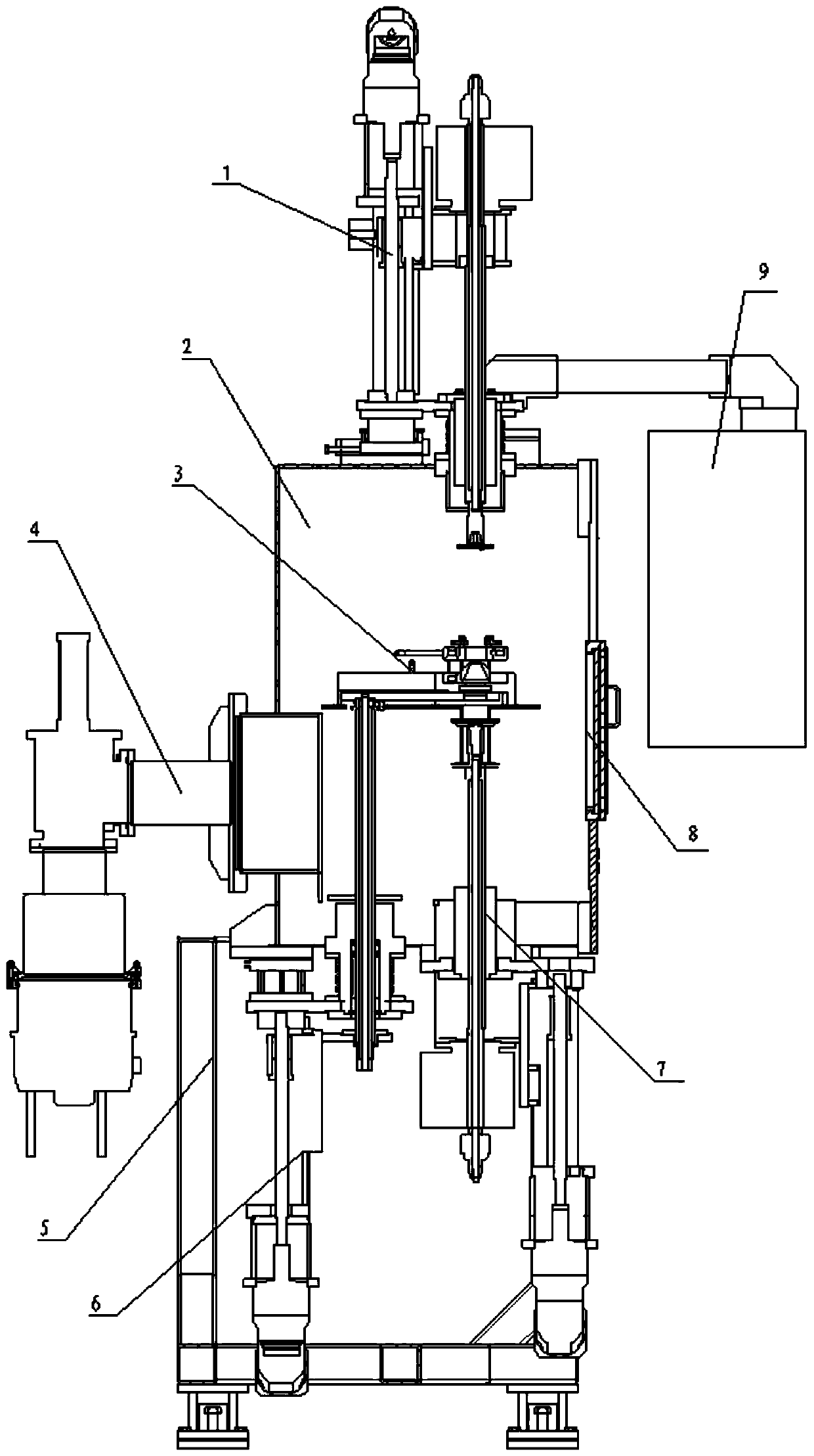
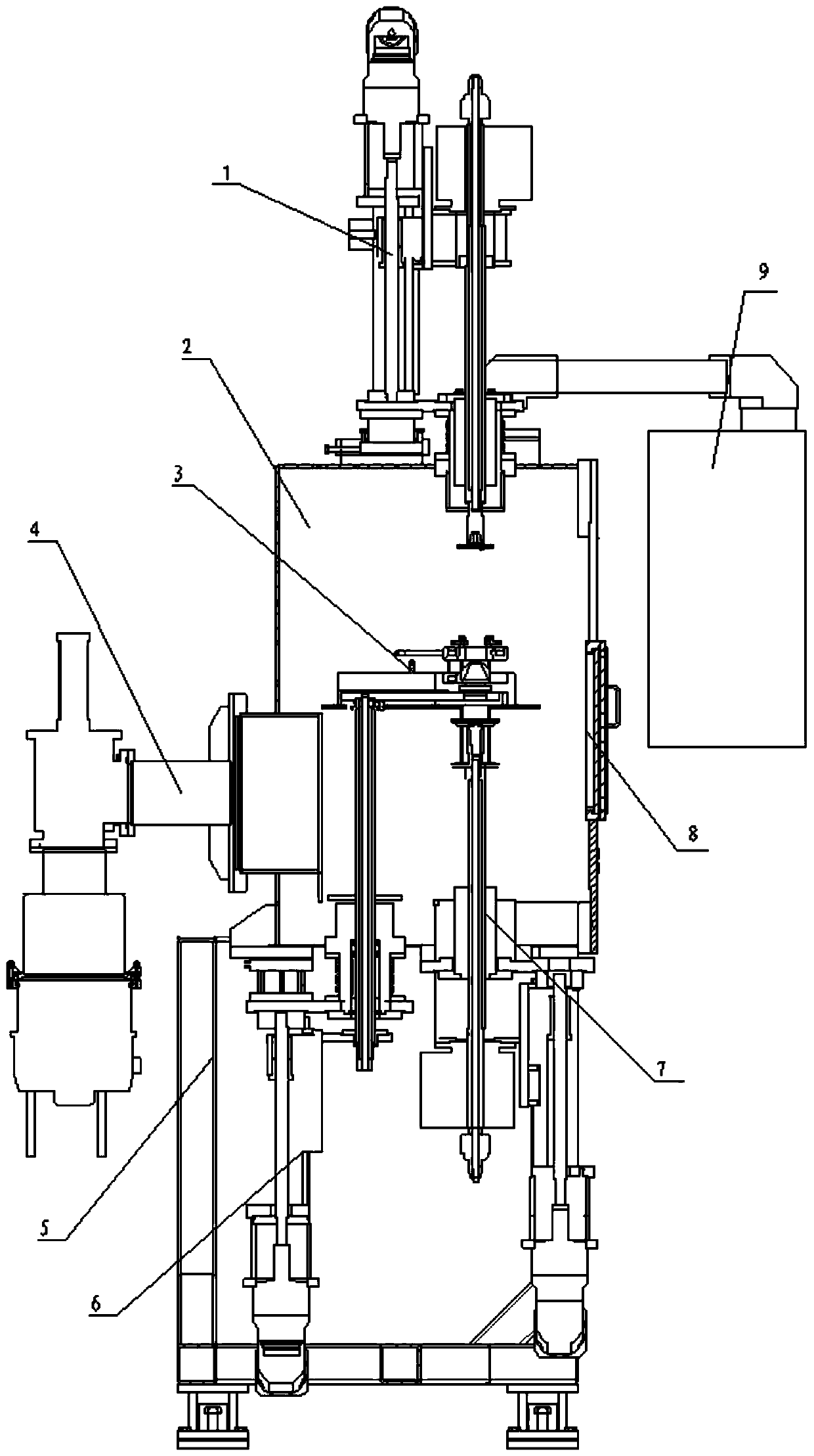
The invention belongs to the technical field of ultra-pure material preparation, and particularly relates to a multifunctional electron beam zone melting furnace. The multifunctional electron beam zone melting furnace comprises an upper feeding and clamping mechanism 1, a furnace body 2, an electronic gun 3, a vacuum system 4, a rack 5, an electronic gun moving mechanism 6, a lower feeding and clamping mechanism 7, an observation window 8, a control box 9, a high-voltage power supply, an automatic control system and a water cooling system; and the end portion, extending into the furnace body 2, of the upper feeding and clamping mechanism 1 is an upper clamping head, and a to-be-melted bar is clamped at the upper clamping head. The function of synchronous coordinated movement of the gun body and the feeding and clamping mechanism can be achieved, diversification of smelting materials can be achieved, the structure is compact, the requirement for smelting of bars with the diameter of 50mm can be met, the layout is reasonable, and maintenance is convenient.

Description


Claims


Application Information

Patent Timeline
Owner GRIMAT ENG INST CO LTD
Why Eureka
Try Eureka