Blowout preventing box

A technology of blowout prevention box and box body, which is applied in drilling equipment, wellbore/well components, earthwork drilling and production, etc., which can solve problems such as troublesome operation, high cost, and aggravated rubber core wear, and achieve cost saving and simple operation Effect

Pending Publication Date: 2020-05-08
YANCHENG DONGRONG PETROLEUM MACHINERY CO LTD
View PDF0 Cites 2 Cited by
  • Summary
  • Abstract
  • Description
  • Claims
  • Application Information

AI Technical Summary

Problems solved by technology

[0002] The blowout prevention box is a tool to prevent the drilling fluid in the lifted drill string from overflowing and polluting the drill floor when the thread of the joint is unloaded when the drill is pulled out. The steel wire rope for traction passes through the rubber core in the blowout prevention box and frequently The rubber core slides, so the rubber core wears quickly and needs to be replaced frequentl

Method used


Image

  • Blowout preventing box
  • Blowout preventing box

Examples


Embodiment Construction

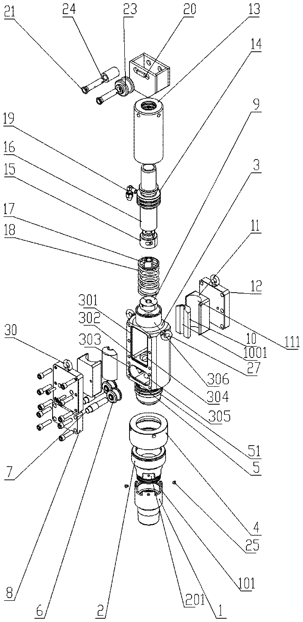
[0016] Such as figure 1 As shown, a blowout prevention box includes a box body 3, a first suspension ring 27, an access assembly, an output assembly and a rubber core; the left and right sides of the box body 3 are provided with a first suspension ring 27 distributed symmetrically; The input component and the output component are respectively arranged at the upper and lower ends of the box body 3, and the rubber core is set inside the box body 3, and the rubber core includes a suction rubber 10, a rubber seat 11, a rubber seat gland 12, a roller gland 8, a Two suspension rings 30, a pulley 6 and a pulley shaft 7; the inside of the box body 3 is provided with a dividing plate 302 distributed horizontally, and a wire hole 304 is provided in the dividing plate 302; The first window 301 of the box body 3 is provided with a second window 303 on the front side of the box body 3, and the two first windows 301 are all arranged on the top of the partition 302, and the second window 303 is


PUM


Abstract

The invention relates to a blowout preventing box. The blowout preventing box comprises a box body, first flying rings, a connecting assembly, an output assembly and a rubber core. The first flying rings are arranged on the left and right sides of the box body symmetrically. The connecting assembly and the output assembly are arranged at the upper and lower ends of the box body correspondingly. The rubber core is arranged in the box body. According to the blowout preventing box, first windows are formed in the front and rear sides of the box body correspondingly, two pumping rubber sheets arefast taken out and replaced by means of two detachable rubber base glands, operation is easy, time and labor are saved, and besides, the cost is saved; and moreover, two pulleys are arranged on the box and matched with a steel wire rope, accordingly, the blowout preventing box is prevented from skewing when the steel wire rope is pulled, and in addition, the wear rate of the rubber core is greatlydecreased.

Description


Claims


Application Information

Patent Timeline
Owner YANCHENG DONGRONG PETROLEUM MACHINERY CO LTD
Why Eureka
Try Eureka