Geological survey equipment and survey method thereof
A geological survey and equipment technology, applied in geological survey equipment and its survey field, can solve problems such as inaccurate measurement results, and achieve the effects of improving accuracy, convenience, and stability
- Summary
- Abstract
- Description
- Claims
- Application Information
AI Technical Summary
Problems solved by technology
Method used
Image


Examples
Embodiment 1
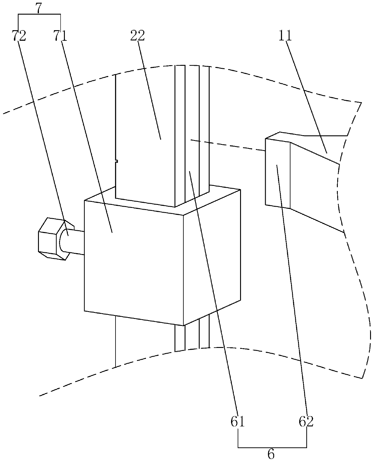
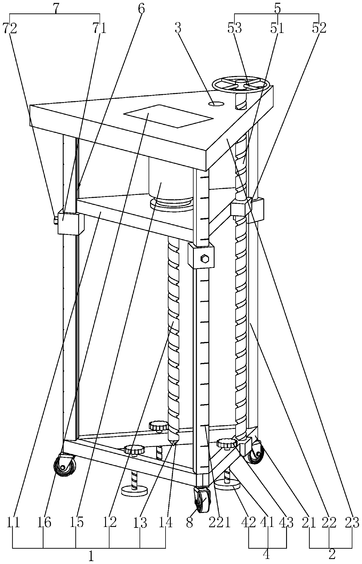
[0040] refer to figure 1 , is a kind of geological survey equipment disclosed by the present invention, comprising a support frame 2 and a surveying device 1, the survey device 1 is arranged in the support frame 2, the support frame 2 includes a cross bar 21, a vertical bar 22 and an operation panel 23, the cross bar 21 There are three vertical bars and vertical bars 22, each horizontal bar 21 is arranged horizontally, and the three horizontal bars 21 are connected from end to end in turn. A leveling assembly 4 is arranged between each horizontal bar 21 and the ground, and the bottom of each horizontal bar 21 Both ends are fixedly connected with universal wheels 8, three vertical bars 22 are all vertically arranged, and the three vertical bars 22 are distributed in a triangle, the bottom of each vertical bar 22 is fixedly connected with the cross bar 21, and the operating panel 23 is horizontally arranged on the vertical The top of the bar 22, the top of each vertical bar 22 is f
Embodiment 2
[0048] A survey method for geological survey equipment, comprising the following steps:
[0049] S1. Leveling the site: Clean up the debris on the surface of the survey site, and then level the survey site.
[0050] S2. Leveling equipment: push the equipment to drive the universal wheel 8 to slide on the ground, push the equipment to the leveled site, turn the leveling handle 43 to drive the screw 51 to rotate, so that the screw 51 pushes the leveling plate 42 to contact the ground, Observe the level situation of the support frame 2 through the universal level bulb 3 on the top of the operation board 23 .
[0051] S3. Adjust the distance between the drill bit 13 and the ground: Turn the lifting handle 53 to drive the screw 51 to rotate around its own axis between the operation panel 23 and the cross bar 21, and the rotation of the screw 51 drives the lifting block 52 to descend along the screw rod, and the lifting block 52 drives the bearing plate 11 to slide downward in the sup
PUM
 Abstract
Description
Claims
Application Information
 - R&D Engineer
- R&D Manager
- IP Professional
- Industry Leading Data Capabilities
- Powerful AI technology
- Patent DNA Extraction
Browse by: Latest US Patents, China's latest patents, Technical Efficacy Thesaurus, Application Domain, Technology Topic.
© 2024 PatSnap. All rights reserved.Legal|Privacy policy|Modern Slavery Act Transparency Statement|Sitemap