Concrete hole wall scrabbling device

A technology of concrete and hole wall, which is applied in the direction of construction, building structure, and building material processing, etc. It can solve the problems that cannot be well adapted to the site construction requirements, it is difficult to control the chisel strength, and the chisel density cannot be adjusted, etc., to achieve Reduce the amount of manual labor, facilitate the construction quality, and have the effect of ingenious structure

Active Publication Date: 2020-07-28
江苏金城建设有限公司
View PDF14 Cites 8 Cited by
  • Summary
  • Abstract
  • Description
  • Claims
  • Application Information

AI Technical Summary

Problems solved by technology

[0006] In view of the above situation, in order to overcome the defects of the prior art, the present invention provides a concrete hole wall chiseling device, which solves the problem of large amount of manpower and difficulty in controlling the chiseling str

Method used


Image

  • Concrete hole wall scrabbling device
  • Concrete hole wall scrabbling device
  • Concrete hole wall scrabbling device

Examples


Embodiment Construction

[0020] The specific implementation manners of the present invention will be further described in detail below in conjunction with the accompanying drawings.

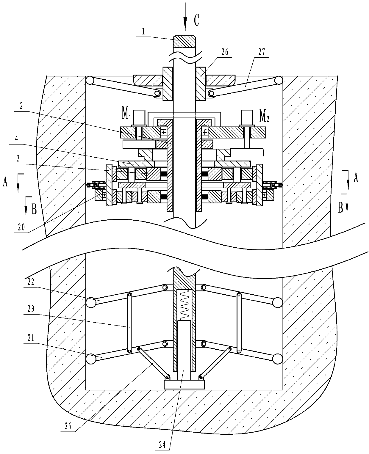
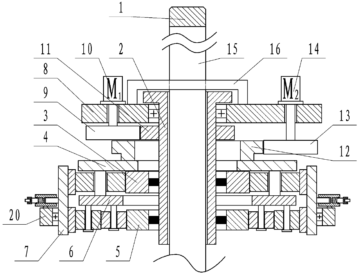
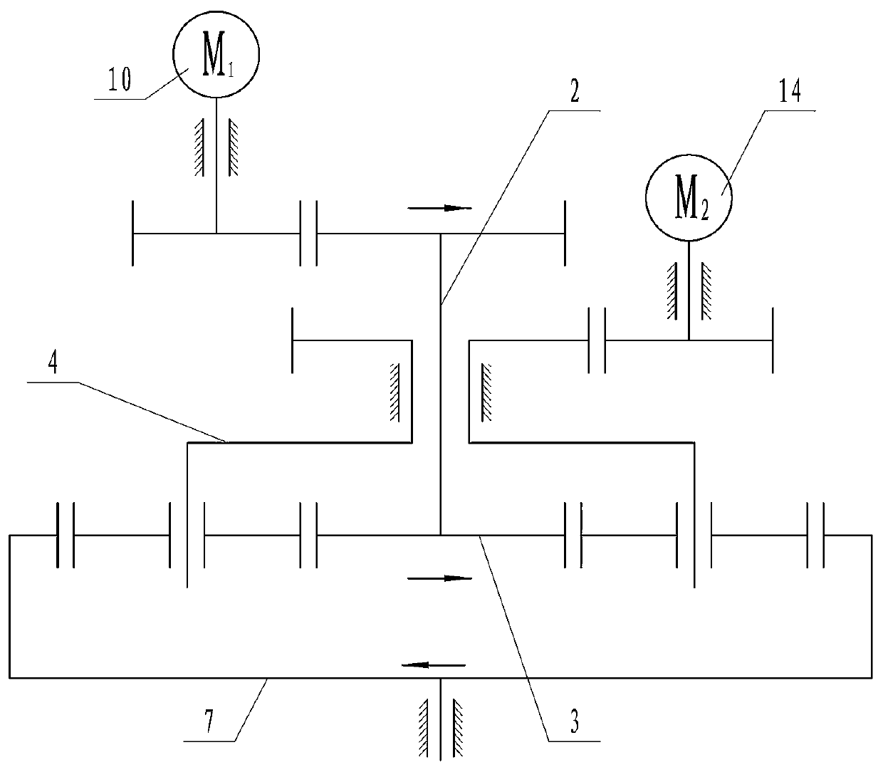
[0021] Depend on Figure 1 to Figure 10 Given, the present invention includes a vertical and non-rotatable screw 1, the screw 1 is placed in the concrete reserved hole and coaxial with it, the screw 1 is sleeved with a threaded tube 2 that can actively rotate, and the threaded tube 2 and the screw 1 Through screw connection, the lower end of the threaded pipe 2 is equipped with a first planetary gear train, wherein the first sun gear 3 in the first planetary gear train is set on the lower end of the threaded pipe 2, and the threaded pipe 2 can drive the first sun gear 3 only when it rotates forward Rotation, the first planetary carrier 4 in the first planetary gear train can actively rotate, the first sun gear 3 in the first planetary gear train is opposite to the rotation direction of the first ring gear; there is a second


PUM


Abstract

The invention provides a concrete hole wall scrabbling device and solves the problems that according to the prior art, great labor force is required in hole wall scrabbling, scrabbling strength cannotbe easily controlled, hole wall scrabbling is uneven, operations are complicated, scrabbling density cannot be adjusted, and onsite construction requirements cannot be duly met. According to the technical scheme, the device comprises a screw rod; the screw rod is provided with a threaded pipe; a first planetary gear system is arranged at the lower end of the threaded pipe; the threaded pipe can only drive a first sun gear to rotate through forward rotation; a first planetary carrier can actively rotate; the rotating direction of the first sun gear is opposite to that of a first gear ring; a second planetary gear system is arranged below the first planetary gear system; a second sun gear is sleeved with the lower end of the threaded pipe; the threaded pipe can only drive the second sun gear to rotate through reverse rotation; the rotating direction of a second gear ring is consistent with that of the second sun gear; the first planetary carrier can drive a second planetary carrier to rotate; a circular cylinder is arranged on the outer side of the first gear ring; and a plurality of circumferentially and evenly distributed scrabbling tools are arranged on the outer side of the circular cylinder.

Description


Claims


Application Information

Patent Timeline
Owner 江苏金城建设有限公司
Why Eureka
Try Eureka