Safe self-driven mechanical arm of rail transit equipment

A technology for rail transit equipment and manipulators, applied in manipulators, animal repellents, manufacturing tools, etc., can solve problems such as disturbing people, inapplicability, safety accidents, etc., and achieve the effect of reducing potential safety hazards and reducing power consumption.

Pending Publication Date: 2020-08-21
CHANGZHOU INST OF LIGHT IND TECH
View PDF0 Cites 0 Cited by
  • Summary
  • Abstract
  • Description
  • Claims
  • Application Information

AI Technical Summary

Benefits of technology

This patented technology allows an autonomous robot called Self Driven Manipulators (SDMs) controlled by its own drive parts and mechanisms to move around on rails without being affected from any bird or animals nearby during operation. It also has a mechanism where it powers up automatically after each movement cycle with minimal energy consumption compared to traditional methods like timers. Overall, this system provides safer and more efficient way to operate railway systems safely.

Problems solved by technology

This patented describes how harmful things can be done by flying fowl like small mammals that live near railway tracks or other structures during their travel through areas where they may come into danger from being attracted towards them. These suspended objects have been known for causing injury when hitting train rails due to falling off trains with these suspending items attached thereto. There currently exist no effective solution available at this time because current solutions require expensive equipment or involve dangerous chemical substances.

Method used


Image

  • Safe self-driven mechanical arm of rail transit equipment
  • Safe self-driven mechanical arm of rail transit equipment
  • Safe self-driven mechanical arm of rail transit equipment

Examples


Embodiment Construction

[0016] The present invention is described in further detail now in conjunction with accompanying drawing. These drawings are all simplified schematic diagrams, which only illustrate the basic structure of the present invention in a schematic manner, so they only show the configurations related to the present invention.

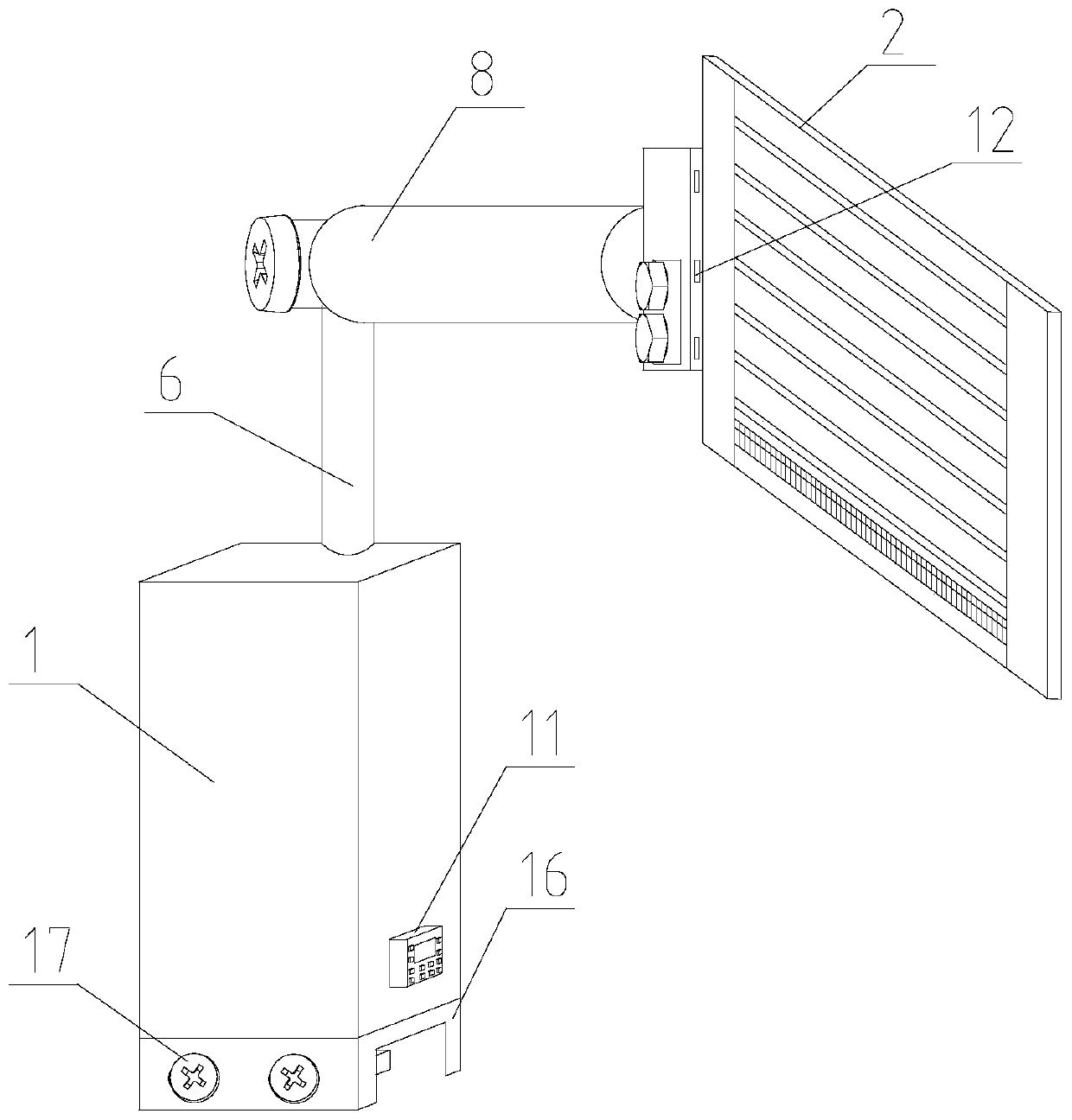
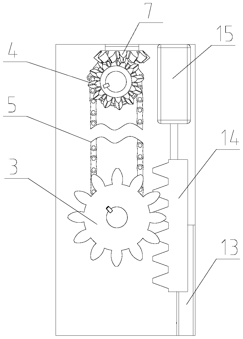
[0017] Such as Figure 1 to Figure 3 The shown rail transit equipment safety self-driving manipulator is the best embodiment of the present invention, including a chassis 1 . A power part and a transmission part connected with the power part are fixed inside the chassis 1 . The lower part of the chassis 1 is fixed with a clamping and fixing part fixed with the bracket. In order to well fix the cabinet 1 and the outdoor equipment, the clamping and fixing part includes a U-shaped channel steel 16 welded and fixed with the cabinet 1, and the side of the U-shaped channel steel 16 is provided with a threaded hole, and the internal thread of the threaded hole is conn


PUM


Abstract

The invention provides a safe self-driven mechanical arm of rail transit equipment. Through cooperation of a driving part and a mechanical structure, reciprocating mechanical swing of a swing hand iscontrolled by controlling the power-on time of a power part, birds are repelled, other photoelectric equipment is not needed, and acousto-optic pollution and resident disturbing phenomena are avoided.Meanwhile, a timing power socket can control the power-on time, so that the electric quantity loss when no birds exist is reduced, the damage of the birds to supports such as a suspension contact netand the like can be effectively reduced, and potential safety hazards are effectively reduced.

Description


Claims


Application Information

Patent Timeline
Owner CHANGZHOU INST OF LIGHT IND TECH
Why Eureka
Try Eureka