Conical barrel type semi-solid metal manufacturing device and use method thereof

A technology of semi-solid metal and preparation equipment, which is applied in the field of cone-type semi-solid metal preparation equipment, which can solve the problems of poor processing effect and small shear force, and achieve the effect of improving the use effect and increasing the shear force

Active Publication Date: 2020-08-21
HEFEI UNIV
View PDF6 Cites 2 Cited by
  • Summary
  • Abstract
  • Description
  • Claims
  • Application Information

AI Technical Summary

Benefits of technology

This new design allows for better control over how much material needs to be processed during production compared to previous designs that had trouble controllably deliver it accurately through gravity-feed systems or other methods like screw conveyors. It also increases the amount of power needed while still providing efficient operation at high speeds.

Problems solved by technology

Technics Problem addressed by this patented technical problem described in the patents involve creation of stable metals (semisolid) through processes like soldering without any residue left behind after melting. Current methods require complete dissolution beforehand, leading to large voids within castings due to insufficient coolant flow around them. Additionally, current techniques result in uneven distribution between two types of molten material - one containing mostly solid particles while another consists only partially liquid. These issues lead to difficulties in achieving desired properties in these alloys.

Method used


Image

  • Conical barrel type semi-solid metal manufacturing device and use method thereof
  • Conical barrel type semi-solid metal manufacturing device and use method thereof
  • Conical barrel type semi-solid metal manufacturing device and use method thereof

Examples


Embodiment 1

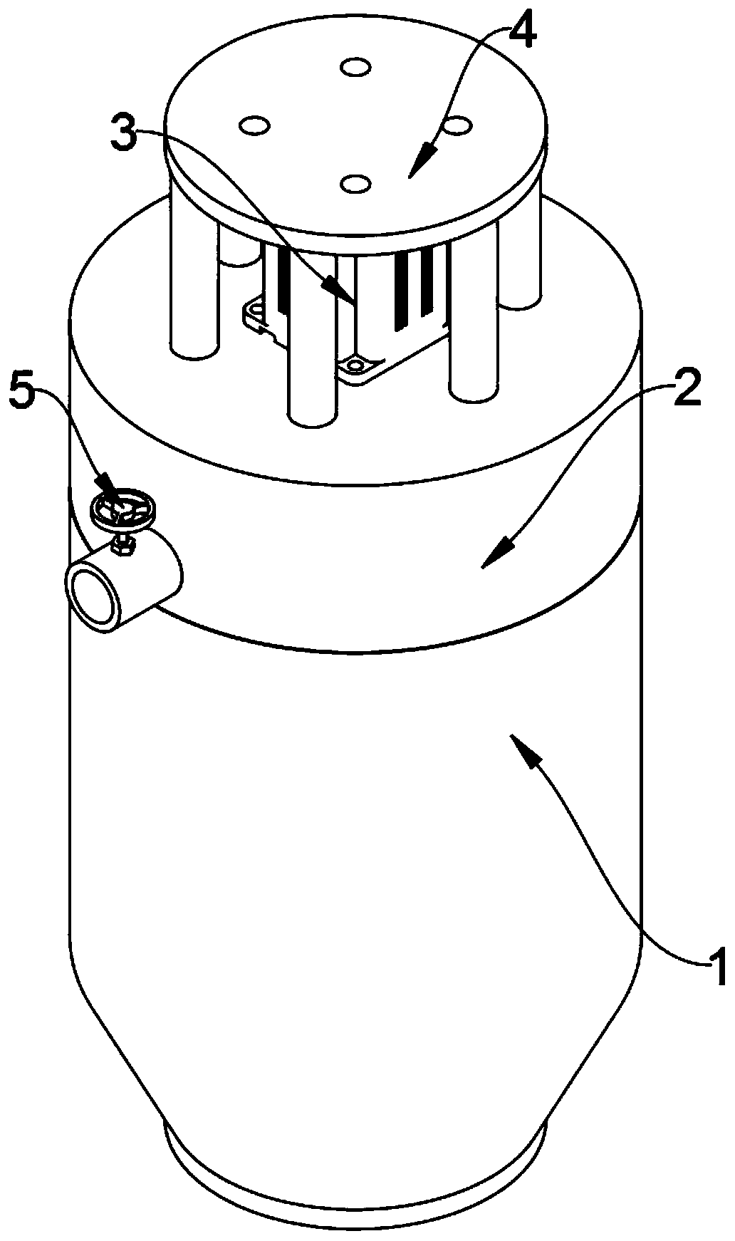
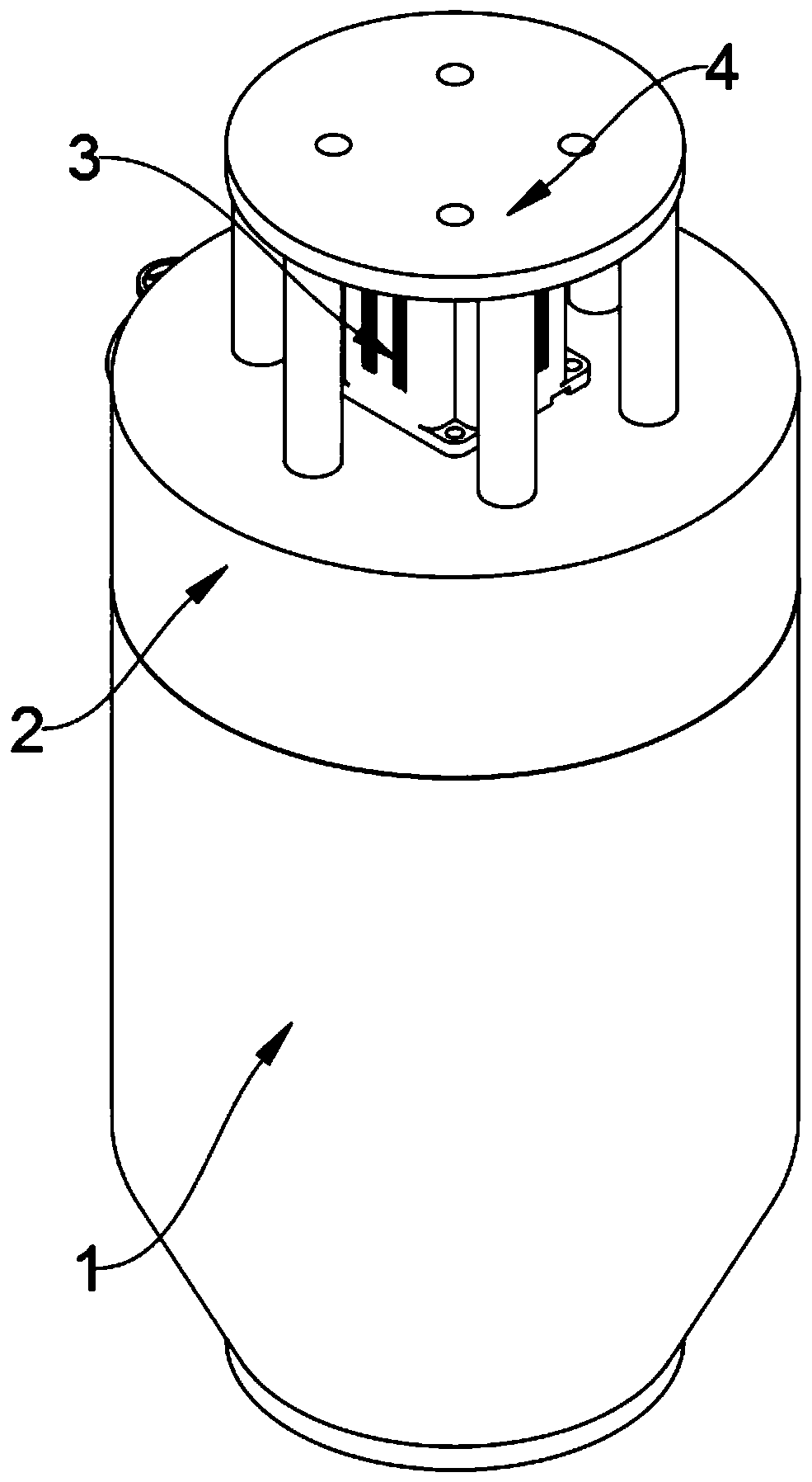
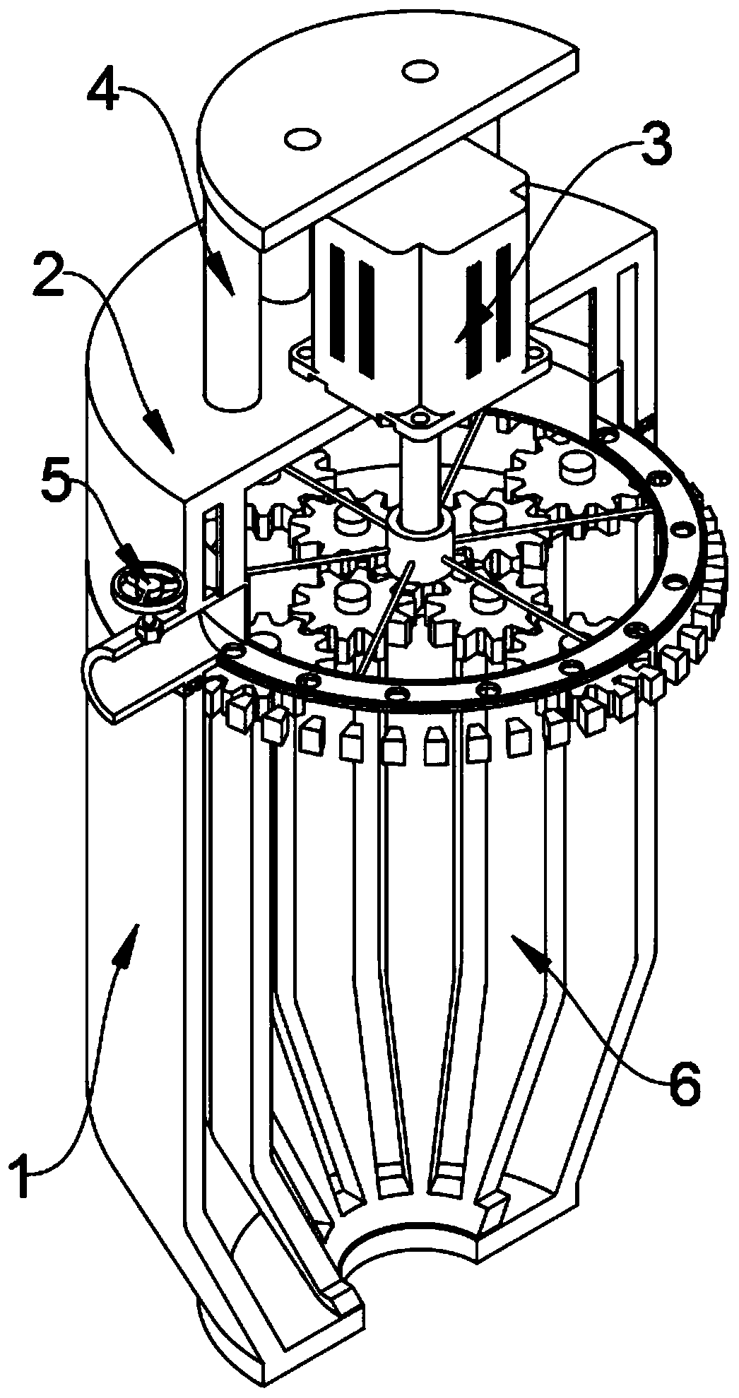
[0036] refer to Figure 1-7 , a cone type semi-solid metal preparation device, comprising a material storage mechanism 1, the material storage mechanism 1 includes a first protective shell 101, a rotating ring 102, a material storage outer cavity 103 and a first discharge port 104, the first protective shell The upper end of 101 is welded with a rotating ring 102, the inside of the first protective shell 101 is provided with a material storage outer chamber 103, and the lower end of the first protective shell 101 is provided with a first discharge port 104, which also includes:

[0037] see Figure 1-5 , the feeding mechanism 2 is located at the upper end of the storage mechanism 1, the feeding mechanism 2 includes a second protective shell 201, an annular feeding pipe 202, a positioning groove 203, a feeding pipe 204, a rotating bottom plate 205, a rotating bracket 206, and a feeding The hole 207 and the connecting rod 208, the lower end of the second protective shell 201 are p

Embodiment 2

[0042] On the basis of the first embodiment, a method for using a cone-barrel semi-solid metal preparation device is disclosed, the steps of which are as follows:

[0043] Step 1: Fix the device on the upper end of the matching lifting mechanism, and then start the lifting mechanism to adjust the position of the device;

[0044] Step 2: Start the servo motor 301 through an external power source electrically connected to the lead wire of the servo motor 301. After the servo motor 301 starts, it will drive the processing mechanism 6 and the second gear 305 to rotate forward through the transmission shaft 302, because the second gear 305 and the third gear 308 are connected by teeth, and when the second gear 305 rotates forward, it will drive the third gear 308 to rotate reversely, because the third gear 308 and the first gear 304 are connected by teeth, and the third gear When 308 rotates reversely, it will drive the first gear 304 to rotate forward, because the first gear 304 and


PUM


Abstract

The invention relates to the technical field of semi-solid metal machining equipment, and discloses a conical barrel type semi-solid metal manufacturing device and a use method thereof. The conical barrel type semi-solid metal manufacturing device comprises a storage mechanism and a feeding mechanism, wherein the storage mechanism comprises a first protection shell, a rotating ring, a storage outer cavity and a first discharge port; the rotating ring is welded and connected to the upper end of the first protection shell; the storage outer cavity is formed in the interior of the protection shell; the first discharge port is formed in the lower end of the protection shell; and the feeding mechanism is positioned at the upper end of the material storage mechanism and comprises a second protection shell, an annular pipe, a positioning groove, a feeding pipe, a rotating bottom plate, rotating supports, discharging holes and connecting rods. According to the conical barrel type semi-solid metal manufacturing device and the use method thereof, the feeding mechanism is arranged, raw materials can be uniformly fed into the storage mechanism, and the fed raw materials are effectively prevented from being stacked together; and a transmission mechanism can drive a machining mechanism and the storage mechanism to rotate in opposite directions, the shearing force formed by the device is increased, and thus the use effect of the device is greatly improved.

Description


Claims


Application Information

Patent Timeline
Owner HEFEI UNIV
Why Eureka
Try Eureka