Hollow shaft sealing ring, hollow shaft, rotor structure, motor and electric vehicle

A technology for sealing rings and hollow shafts, which is applied in the fields of hollow shafts, motors and electric vehicles, rotor structures, and hollow shaft sealing rings, and can solve problems such as negative pressure that cannot normally throw oil

Active Publication Date: 2020-08-21
GREE ELECTRIC APPLIANCES INC
View PDF32 Cites 1 Cited by
  • Summary
  • Abstract
  • Description
  • Claims
  • Application Information

AI Technical Summary

Benefits of technology

This patented design helps keep lubricating oils inside an engine's housing while still allowing for efficient rotation without leakage or overheating. It also prevents excessive pressurization caused by changes made during operation due to temperature differences that may affect other parts within the system.

Problems solved by technology

This technical problem addressed by this patented describes how to efficiently remove excessive amounts of heat generated when operating vehicles under heavy load conditions while maintaining their ability to operate effectively without overheated components or causing damage caused by too much torsion force applied thereto.

Method used


Image

  • Hollow shaft sealing ring, hollow shaft, rotor structure, motor and electric vehicle
  • Hollow shaft sealing ring, hollow shaft, rotor structure, motor and electric vehicle
  • Hollow shaft sealing ring, hollow shaft, rotor structure, motor and electric vehicle

Examples


Embodiment Construction

[0028] In order to make the purpose, technical solution and advantages of the present invention clearer, the technical solution of the present invention will be clearly and completely described below in conjunction with specific embodiments of the present invention and corresponding drawings. Apparently, the described embodiments are only some of the embodiments of the present invention, but not all of them. Based on the embodiments of the present invention, all other embodiments obtained by persons of ordinary skill in the art without making creative efforts belong to the protection scope of the present invention.

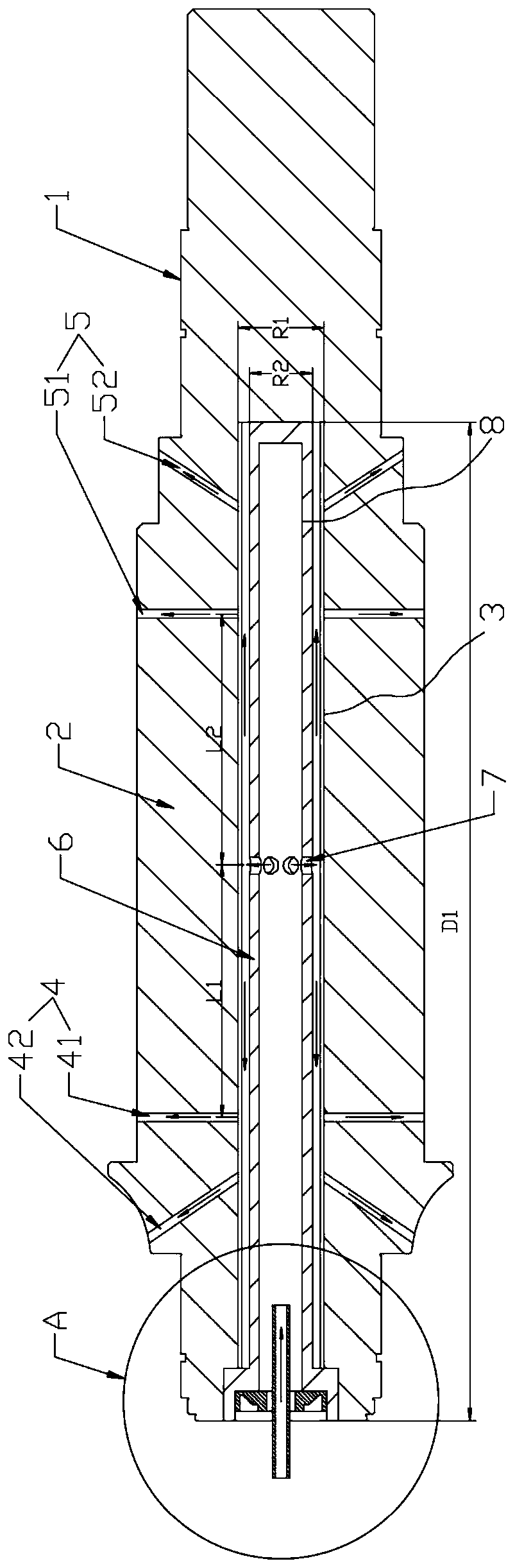
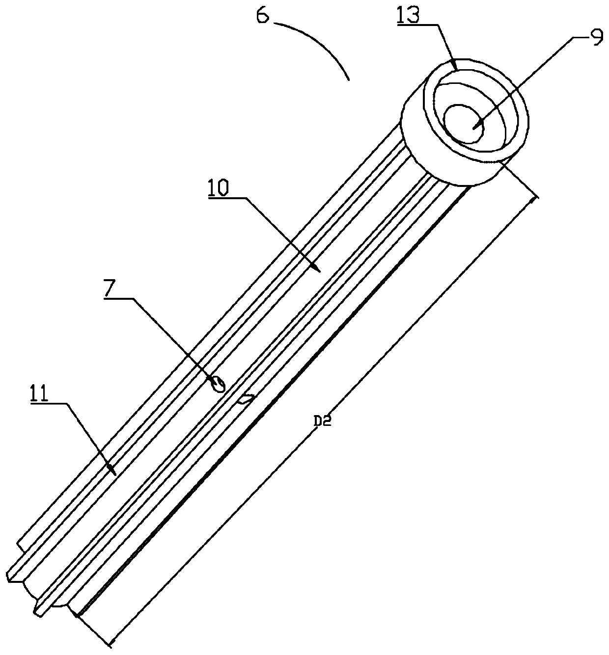
[0029] combine Figure 1 to Figure 8 As shown, a hollow shaft 1 disclosed in the embodiment of the present invention includes: a shaft body 2, the shaft body 2 is provided with a shaft cavity 3 with one end open; At least one second end oil throwing port 5; casing part 6, the casing part 6 is arranged in the shaft cavity 3, the casing part 6 is provided with an oil


PUM


Abstract

The invention provides a hollow shaft sealing ring, a hollow shaft, a rotor structure, a motor and an electric automobile, wherein the hollow shaft sealing ring is used for sealing an oil inlet of thehollow shaft, an oil pipe hole is formed in the sealing ring, an oil inlet pipe is arranged in the oil pipe hole, the outer diameter of the oil inlet pipe is R5, the inner diameter of the oil pipe hole is R4, and R4 is larger than R5. According to the semi-closed sealing structure of the hollow shaft, cooling oil can be prevented from leaking along the inner wall of the bushing cavity when the rotor rotates at a high speed while the bushing cavity can be kept communicated with the outside, and the situation that oil cannot be sprayed due to the fact that pressure difference is formed betweenair pressure of the inner cavity and the outside of the oil throwing opening is avoided.

Description


Claims


Application Information

Patent Timeline
Owner GREE ELECTRIC APPLIANCES INC
Why Eureka
Try Eureka