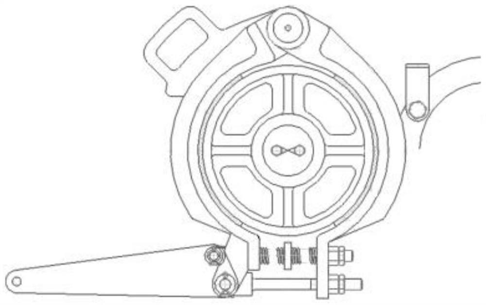
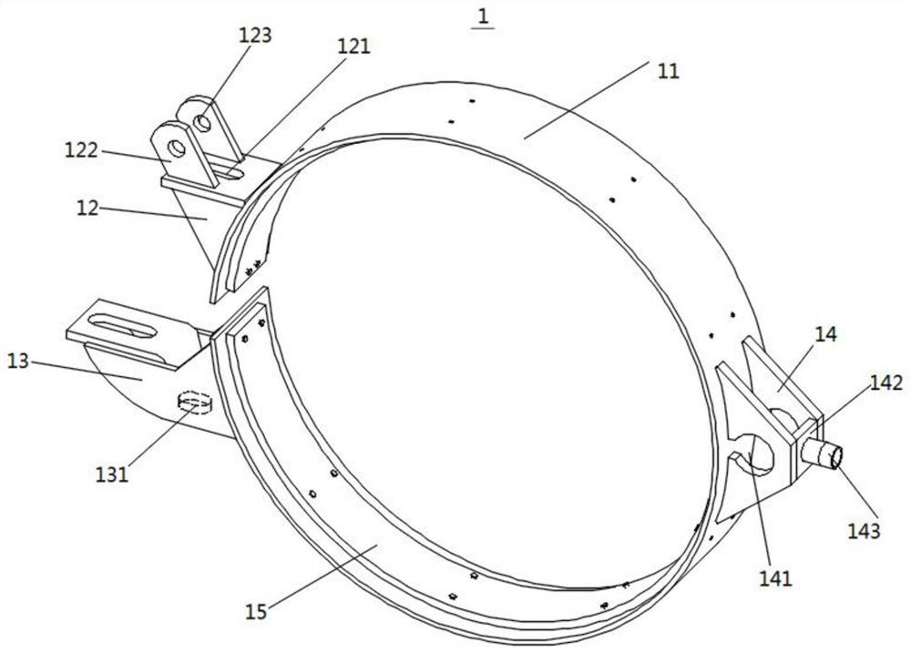
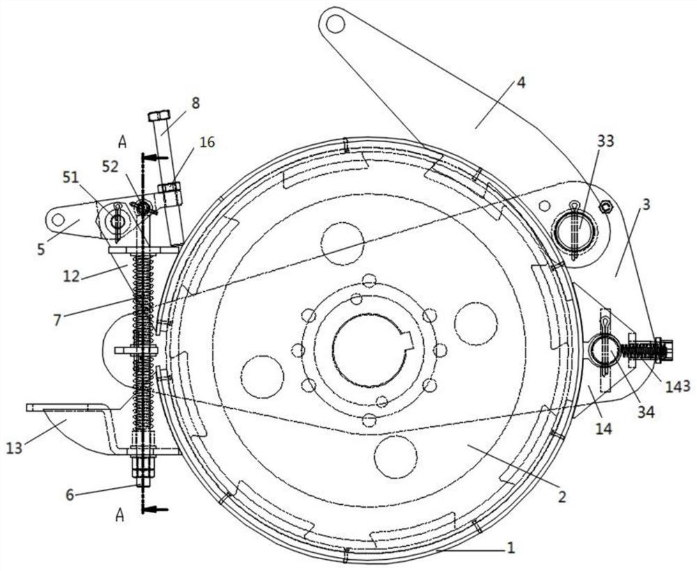
Brake ring of pumping unit reducer and brake structure

A machine reducer and brake ring technology, which is applied in the field of pumping unit reducer brake ring and pumping unit reducer brake structure, can solve the problems of scrapped brake wheels, high rigidity, and unstable connection

Pending Publication Date: 2020-09-22
CHENGDU XINZE MACHINERY
View PDF0 Cites 0 Cited by
  • Summary
  • Abstract
  • Description
  • Claims
  • Application Information

AI Technical Summary

Benefits of technology

This innovative design allows for better control during shaving operations while maintaining accurate positioning accuracy when attaching brackets onto an engine's reduction gearbox (R). It eliminated any issues like excessive wearing out of worn parts such as brakes and reduced efficiency associated therewith. Additionally, this new structure makes maintenance easier because no loose components are needed instead of requiring regular adjustments. Overall, these technical improvements improve performance and durability of reducing machines used at home.

Problems solved by technology

This technical problem addressed in this patents relates to improving the reliability and economy efficiency of the Pumping Unit Reducer (PUL) without compromising on their ability to prevent accidents such as unexpected stops caused by external factors like shock waves or impacts.

Method used


Image

  • Brake ring of pumping unit reducer and brake structure
  • Brake ring of pumping unit reducer and brake structure
  • Brake ring of pumping unit reducer and brake structure

Examples


Embodiment Construction

[0037] The present invention will be further described below in conjunction with accompanying drawing.

[0038] In the description of the present invention, it should be noted that the terms "center", "upper", "lower", "left", "right", "vertical", "longitudinal", "lateral", "horizontal" , "Inner", "Outer", "Front", "Back", "Top", "Bottom" and other indicated orientations or positional relationships are based on the orientations or positional relationships shown in the attached drawings, or when the inventive product is used Orientation or positional relationship that is conventionally placed is only for the convenience of describing the present invention and simplifying the description, and does not indicate or imply that the referred device or element must have a specific orientation, be constructed and operated in a specific orientation, and therefore cannot be construed as a reference to the present invention. Invention Limitations. In addition, the terms "first", "second", "


PUM


Abstract

The invention discloses a brake ring of a pumping unit reducer, and relates to the field of oil exploitation. The brake ring of the pumping unit reducer comprises a brake ring main body, wherein the brake ring main body is an open circle, the inner surface of the brake ring main body is provided with a brake band, one end of the brake ring main body is provided with a first pressing part, the other end is provided with a second pressing part, and one end of the brake ring main body is also provided with a connection fixing part. The brake ring has the advantages of low manufacturing cost, safety and labor saving.

Description


Claims


Application Information

Patent Timeline
Owner CHENGDU XINZE MACHINERY
Why Eureka
Try Eureka