Magnetic suspension type side pressure one-way micro-power piezoelectric inertia driver

A driver and micro-power technology, applied to piezoelectric effect/electrostrictive or magnetostrictive motors, magnetic attraction or thrust holding devices, electrical components, etc., can solve problems such as output performance changes and inability to move

Active Publication Date: 2020-09-29
ZHEJIANG NORMAL UNIV XINGZHI COLLEGE
View PDF7 Cites 0 Cited by
  • Summary
  • Abstract
  • Description
  • Claims
  • Application Information

AI Technical Summary

Benefits of technology

The technical effect described in this patented technology allows for better control over how far drivers are from their car's seat when they carry heavy weights on them while still being able to maintain consistence within certain limits during operation. This ensures stable driving performance regardless if there were slight variations or changes made afterwards due to factors like road conditions or other environmental variables such as temperature.

Problems solved by technology

This patented technical solution describes how to improve the efficiency and accuracy of piezeoptic motors used as driving platforms for applications such as microscope scanners. These systems require precise position feedback signals to ensure accurate operation over long distances without any variations caused by external factors like weight distribution or temperature variation. Additionally, these solutions involve controllable electrostatic thrust generators made up of multiple small capacitors connected together through gears called diaphragms. To prevent backlash effects, certain types of materials may be added at specific locations along the actuation path.

Method used


Image

  • Magnetic suspension type side pressure one-way micro-power piezoelectric inertia driver
  • Magnetic suspension type side pressure one-way micro-power piezoelectric inertia driver

Examples


Embodiment Construction

[0028] The following are specific embodiments of the present invention and in conjunction with the accompanying drawings, the technical solutions of the present invention are further described, but the present invention is not limited to these embodiments.

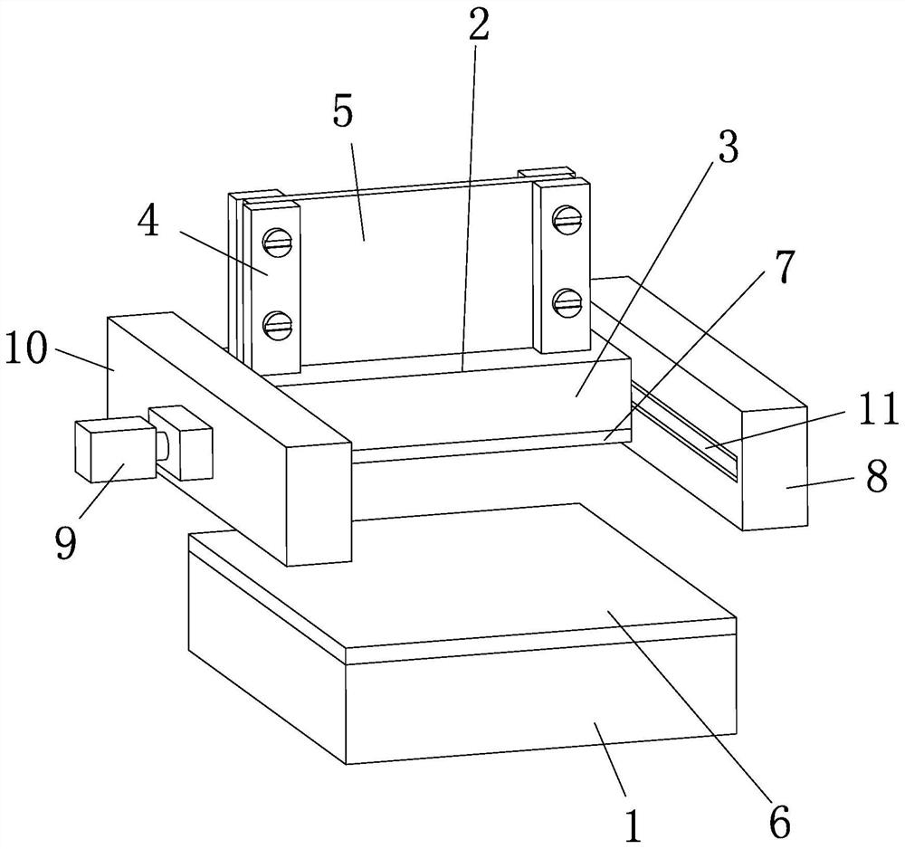
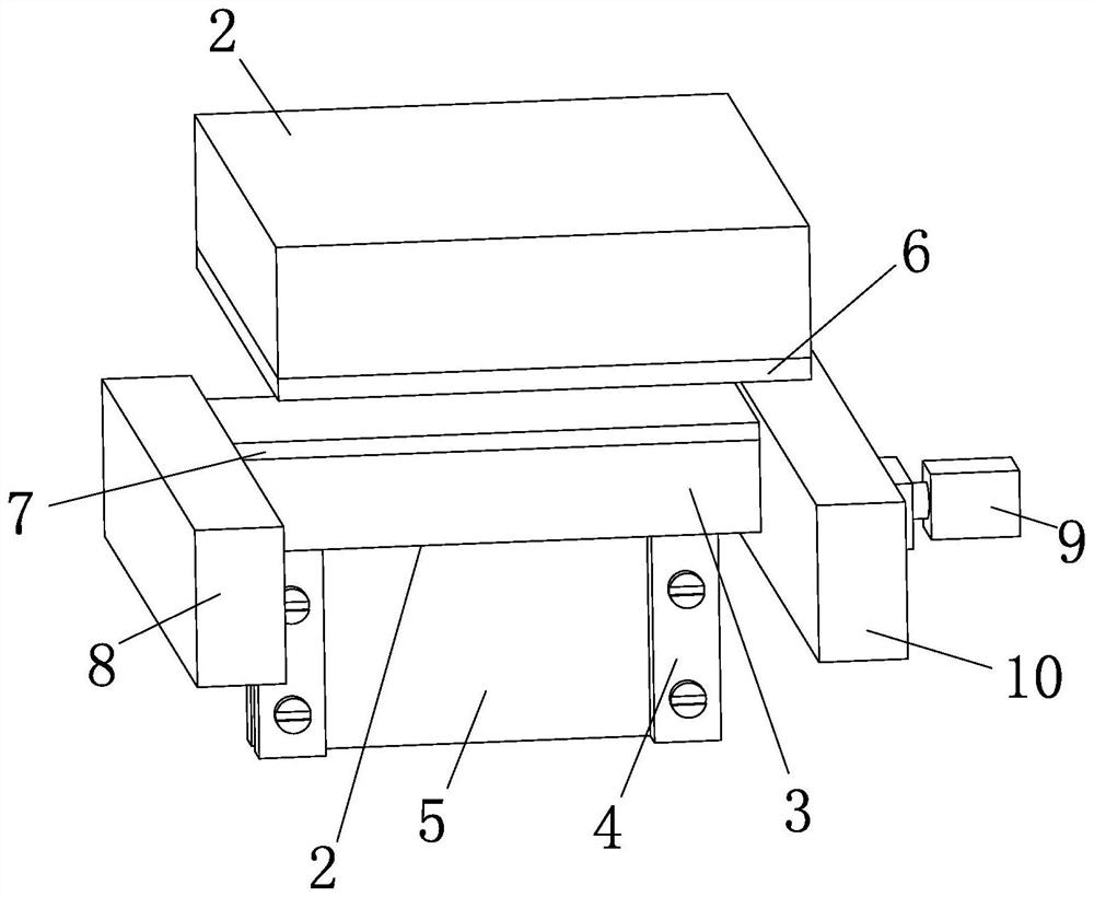
[0029] Such as figure 1 and figure 2 As shown, the magnetic levitation type side pressure unidirectional microdynamic piezoelectric inertia driver includes a bracket body 1 and a driver body 2, the driver body 2 includes a bracket block 3, a pressure plate 4 fixedly arranged on the bracket block 3, and the edges are clamped on the pressure plate 4 The piezoelectric sheet 5 on the top of the piezoelectric sheet 5 is electrically connected with an asymmetric waveform electric signal.

[0030] During operation, the piezoelectric sheet 5 is excited by an asymmetric waveform electric signal, so that the piezoelectric sheet 5 generates inertial impact forces of different magnitudes in the positive and negative directions.

[003


PUM


Abstract

The invention provides a magnetic suspension type side pressure one-way micro-power piezoelectric inertia driver, and belongs to the technical field of precision motion driving elements. The problem that after an existing piezoelectric actuator carries an external load, the output performance is changed, and even the piezoelectric actuator cannot move is solved. The piezoelectric inertial driver comprises a bracket body and a driver body, and a forward magnet is fixedly arranged on the bracket body; a floating acting body is fixedly arranged on the bracket block; the forward magnet and the floating action body cover the opposite faces of a bracket body and the support block and cover the whole surface, the outer side face of the forward magnet and the outer side face of the floating actionbody are planes and are parallel to each other all the time, and the floating action body is a reverse permanent magnet with magnetism or a magnet which does not have magnetism and can be attracted by magnetic force. Compared with the prior art, the same step pitch can be output after different mass loads are carried on the premise of not carrying out any debugging.

Description


Claims


Application Information

Patent Timeline
Owner ZHEJIANG NORMAL UNIV XINGZHI COLLEGE
Why Eureka
Try Eureka