Vaginal dilator for cervical examination and surgery
A technique for vaginal dilation and surgery, applied in the directions of surgery, colposcopy, application, etc., can solve the problems of fracture, cannot be used again, and is difficult to break, and achieve the effect of improving inspection and surgical conditions
- Summary
- Abstract
- Description
- Claims
- Application Information
AI Technical Summary
Benefits of technology
Problems solved by technology
Method used
Image

Examples
Embodiment 1
[0080] Inspection type four-wing vaginal dilator
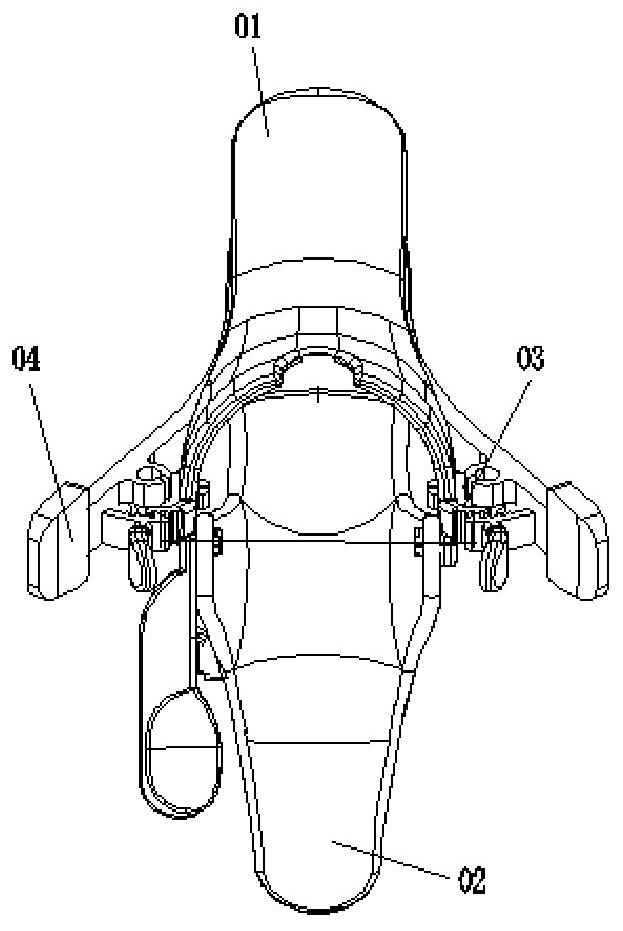
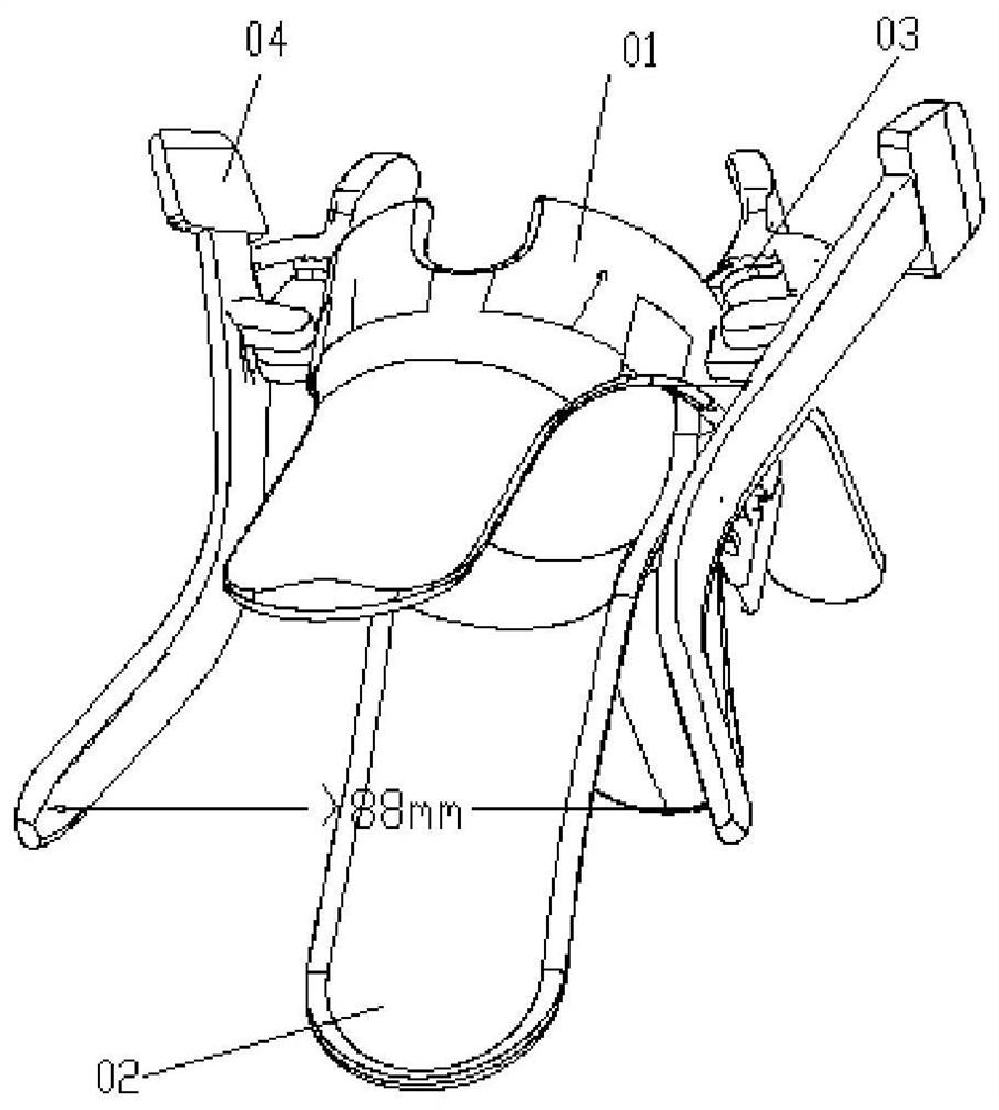
[0081] first refer to attached figure 1 with 4 -5, inspection-type four-wing vaginal dilator includes: an upper expansion piece 01, including an upper wing 01-1, and a handle 01 that is integrated with the upper wing 01-1 and extends downward along the rear end of the upper wing -2, a lower expansion piece 02, the lower expansion piece 02 includes a lower wing 02-1, a handle that is integrated with the lower wing 02-1, and extends downward along the lower wing 02-1 in a direction close to a right angle 02-2, on both sides of the rear end of the upper wing 01-1 and the lower wing 02-1, respectively use the pivot pin 01-3 and the shaft hole 02-5 to connect, so the upper wing 01-1 and the lower wing 02-1 can pass through 01-2 opening and closing of the control button.
[0082] A first expanding and fixing device for fixing the opened state of the upper wing 01-1 and the lower wing 02-1, the device further includes a positioning h
Embodiment 2
[0091] Four-wing vaginal dilator for cervical surgery
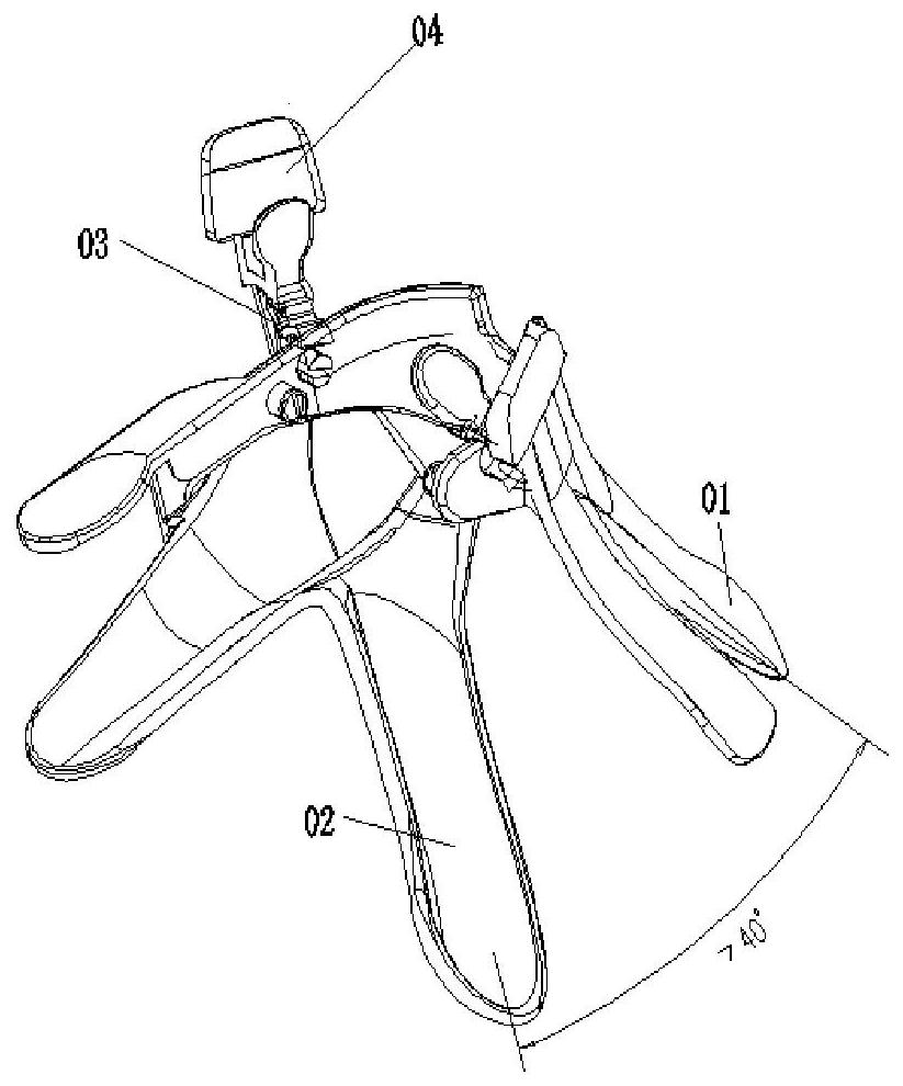
[0092] The structure of the vaginal dilator of the present embodiment is the same as that of the vaginal dilator of the embodiment 1 except that the side dilator is different, and the others are all identical to the inspection type four-wing vaginal dilator of the embodiment 1, so the same parts are no longer For details, see Figure 8 , the side expansion piece 04 of the four-winged vaginal dilator for cervical surgery is hollow and has a channel, and the channel 04-12 is composed of the channel body 04-11 and the channel cover 04-13 on it, and the inner side, upper side or lower side of the front end is set There is at least one opening communicating with the channel 18, and the rear end is a pipe joint.
[0093] see Image 6 , 8 -10. In this embodiment, the pivot pin 04-18 of the side expansion sheet is connected to the shaft hole 03-22 of the positioning connector, and the pivot pin 03-21 of the positioning connector
Embodiment 3
[0100] Destroyable inspection type four-wing vaginal dilator
[0101] The structure of the vaginal dilator of the present embodiment is different from the structure of the vaginal dilator of the embodiment 1, except that the handle of the lower dilator of the present embodiment has an instant destruction strip, and the rest are the same as the inspection type four-winged vagina of the embodiment 1. The dilators are exactly the same, so the same parts will not be repeated, please refer to Figure 13 , the handle 02-4 of the lower expansion piece 02 is provided with an instant destroying strip 02-10, the front end of the instant destroying strip 02-10 passes through a tie 02-11, and its rear end passes through a material reducing groove 02-12 and the handle 02-4 is connected, and its left and right sides are hollow windows 02-13, and there is a small protrusion 02-14 higher than the handle 02-4 plane above the middle of the destroyable bar 02-10. The instant destroy strip has thre
PUM
 Abstract
Description
Claims
Application Information
 - R&D Engineer
- R&D Manager
- IP Professional
- Industry Leading Data Capabilities
- Powerful AI technology
- Patent DNA Extraction
Browse by: Latest US Patents, China's latest patents, Technical Efficacy Thesaurus, Application Domain, Technology Topic.
© 2024 PatSnap. All rights reserved.Legal|Privacy policy|Modern Slavery Act Transparency Statement|Sitemap