Air purifier

An air purifier and air outlet technology, applied in the field of air purification, can solve problems such as low air purification efficiency and difficulty in determining liquid flow, and achieve the effect of improving purification efficiency

Pending Publication Date: 2020-12-01
GD MIDEA AIR-CONDITIONING EQUIP CO LTD +1
View PDF0 Cites 2 Cited by
  • Summary
  • Abstract
  • Description
  • Claims
  • Application Information

AI Technical Summary

Benefits of technology

The technical effect of this innovation is that it allows for precise control over how much fluid flows through different parts inside the cleaner's tank based upon its own internal design or specific characteristics such as lifespan and performance. This helps improve the overall functioning of the device while reducing costs associated therewith.

Problems solved by technology

The technical problem addressed by this patented technology relates to determining which amount of water needs for an indoor unit (I) during operation based on factors like how well they are doing with each other or their surrounding environment such as temperature conditions.

Method used


Image

  • Air purifier
  • Air purifier
  • Air purifier

Examples


Embodiment Construction

[0038] Embodiments of the present invention are described in detail below, examples of which are shown in the drawings, wherein the same or similar reference numerals designate the same or similar elements or elements having the same or similar functions throughout. The embodiments described below by referring to the figures are exemplary only for explaining the present invention and should not be construed as limiting the present invention.

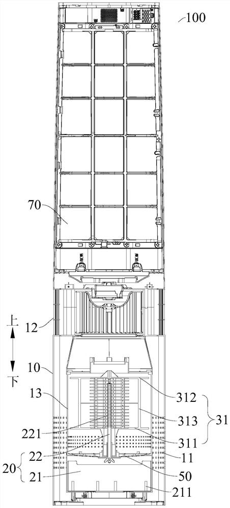
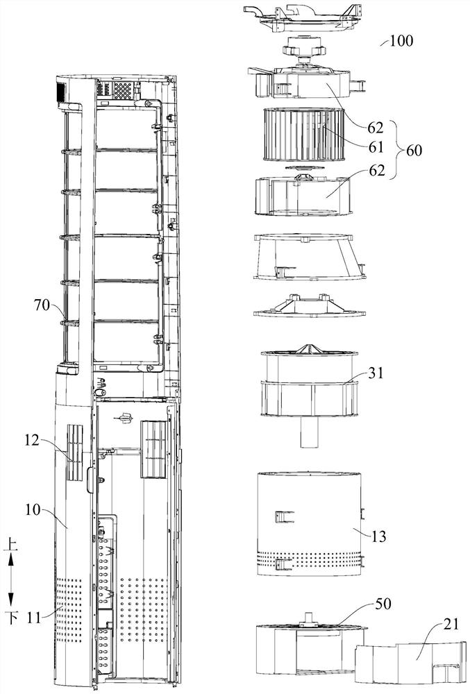
[0039] Refer below Figure 1-Figure 3 The air purifier 100 according to the embodiment of the present invention will be described, and the air purifier 100 can be used to purify indoor air.

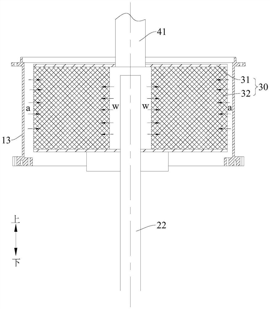
[0040] Such as figure 1 As shown, the air cleaner 100 according to the embodiment of the present invention includes a housing 10 , a water supply device 20 and a rotating body 30 .

[0041] Specifically, the housing 10 has an air inlet 11 and an air outlet 12 , and an accommodation chamber is defined inside the housing 10 , and the accommodation cham


PUM


Abstract

The invention discloses an air purifier comprising: a shell having an air inlet and an air outlet, the shell defining an accommodating cavity communicating with an air inlet and an air outlet; a watersupply device which comprises a water tank and a water distribution pipe, wherein the water tank is communicated with the water distribution pipe through a water inlet pipe, and a plurality of waterspraying openings are formed in the water outlet end of the water distribution pipe; a rotating body which is rotatably arranged in the accommodating cavity, wherein the rotating body and the inner side wall of the shell are arranged in a spaced mode; the rotating body scatters water liquid sprayed into the rotating body and throws the water liquid to the inner side wall of the containing cavity,the inner diameter of the water distribution pipe is D1, L is the liquid flow, and V1 is the liquid flow speed. According to the air purifier provided by the embodiment of the invention, the air purification efficiency can be improved according to the flow change.

Description


Claims


Application Information

Patent Timeline
Owner GD MIDEA AIR-CONDITIONING EQUIP CO LTD
Why Eureka
Try Eureka