Filter pressing unit and filter press

A filter unit and guide sleeve technology, applied in water/sludge/sewage treatment, chemical instruments and methods, sludge treatment, etc., can solve the problems of lateral deformation of springs, tilting of filter presses, unbalanced force, etc. Achieve the effect of improving verticality and parallelism, ensuring axial force and verticality, and improving parallelism and verticality

Pending Publication Date: 2020-12-25
华汇生态环境产业有限公司
View PDF1 Cites 0 Cited by
  • Summary
  • Abstract
  • Description
  • Claims
  • Application Information

AI Technical Summary

Benefits of technology

This patented technology allows for better control over filters used in industrial processes such as oil refining or waste water treatment systems. By moving one part (the header) away while keeping other parts fixed, more precise alignment may occur with respect to the connections within the system without any issues like misalignment or damage caused due to external forces acting upon them. Additionally, this design prevents leaks through gaps creating cracks which could cause problems if they were allowed too much fluid into the filtered material being treated. Overall, these improvements enhance the performance and efficiency of the overall equipment involved in processing industries.

Problems solved by technology

This patented technical problem addressed in this patents relates to improving the performance of filters for use in industrial processes like wastewater treatment plants due to increasing productivity without compromising safety concerns associated with conventional filtering systems. Multi-stage filtration has been developed but current techniques require longer connections than desired because they cause disturbances from weight distribution and forces caused by springs. Additionally, these issues lead to uneven pressure across different parts of the system leading to reduced overall functionality overall.

Method used


Image

  • Filter pressing unit and filter press
  • Filter pressing unit and filter press

Examples


Embodiment Construction

[0023] The present invention will be described in detail below in conjunction with the accompanying drawings. When describing the embodiments of the present invention in detail, for the convenience of explanation, the accompanying drawings showing the structure of the device will not be partially enlarged according to the general scale, and the schematic diagram is only an example, and it should not be limited here. The protection scope of the present invention. It should be noted that the drawings are in simplified form and use inaccurate scales, which are only used to facilitate and clearly assist the purpose of illustrating the embodiments of the present invention.

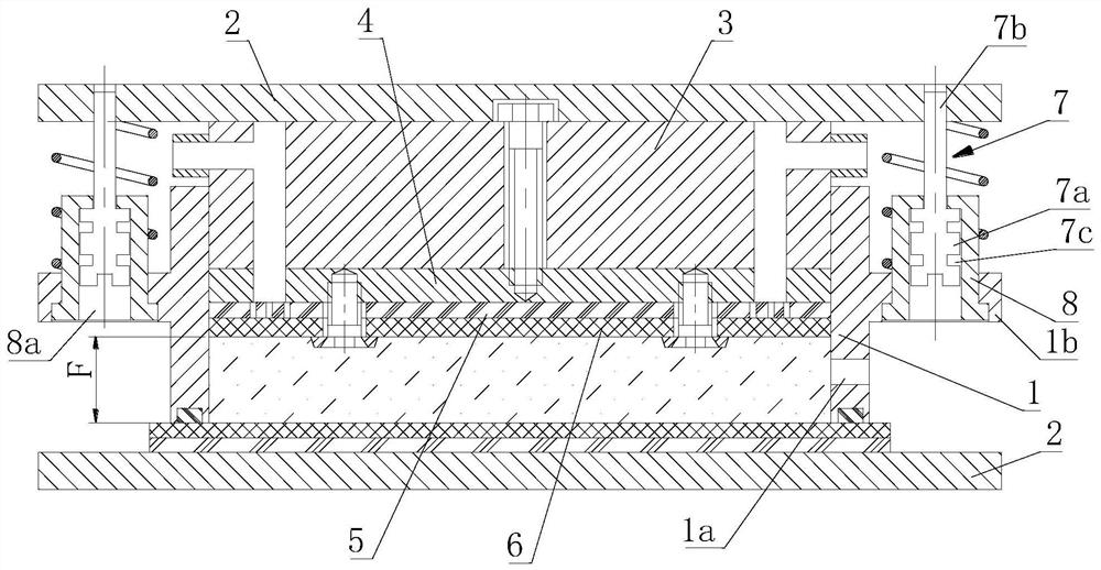
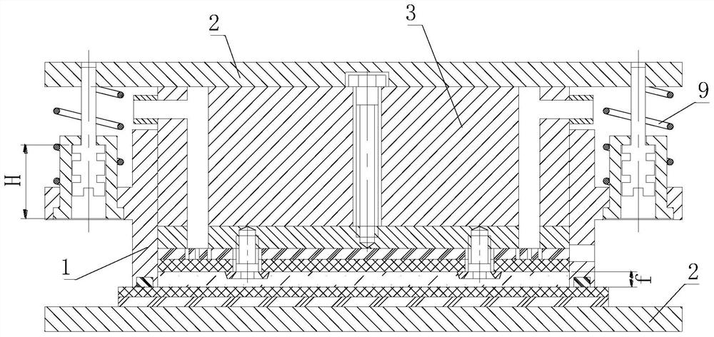
[0024] The filter press mainly includes a frame, a filter cylinder, a pressure plate and a filter plate (filter cloth, filter screen), among which the piston (also called a pressure plate), the filter plate assembly and the filter cylinder constitute the filter unit of the filter press. . The multi-layer filter p


PUM


Abstract

The invention provides a filter pressing unit, which comprises a filter pressing cylinder, a piston arranged in the filter pressing cylinder and a connecting plate for supporting the filter pressing cylinder; the upper and lower adjacent filter pressing units are separated by a connecting plate, and the filter pressing cylinder is movably connected with the connecting plate positioned above the filter pressing cylinder through a connecting assembly; the connecting assembly comprises: a guide sleeve, which is connected with the filter pressing cylinder and is provided with an inner cavity, theaxis of which is parallel to the axis of the filter pressing cylinder; a connecting bolt, which is connected with the guide sleeve, has the head arranged in the inner cavity of the guide sleeve and the tail connected with a connecting plate located above the filter pressing cylinder, wherein the connecting bolt and the guide sleeve can relatively move in the axial direction of the inner cavity, and the head and the guide sleeve form axial limiting so that the connecting bolt and the guide sleeve cannot be separated in the axial direction; and a spring, which is sleeved outside the guide sleeve, and has one end propped against the filter pressing cylinder and the other end propped against the connecting plate positioned above the filter pressing cylinder. Balanced stress can be achieved during filter pressing, and the motion parallelism and perpendicularity of all parts of the filter pressing unit are guaranteed.

Description


Claims


Application Information

Patent Timeline
Owner 华汇生态环境产业有限公司
Why Eureka
Try Eureka