Infrared burner
An infrared burner and external combustion technology, applied in the field of cookers, can solve problems such as insufficient combustion, and achieve the effects of sufficient combustion, reducing temperature rise, and improving combustion thermal efficiency
- Summary
- Abstract
- Description
- Claims
- Application Information
AI Technical Summary
Benefits of technology
Problems solved by technology
Method used
Image

Examples
Embodiment 1
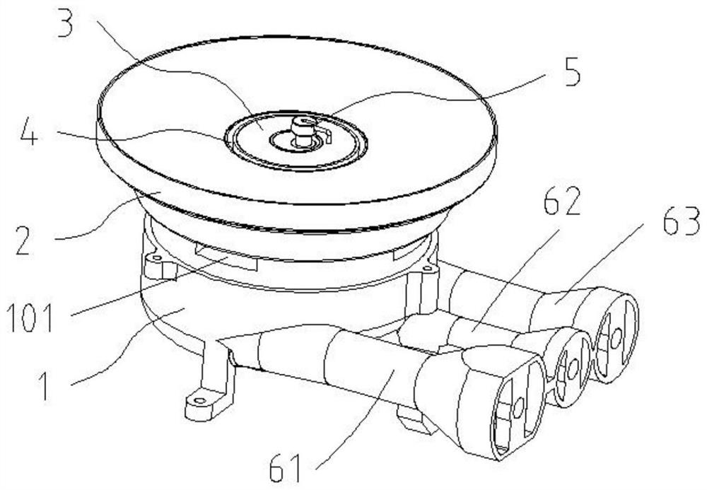
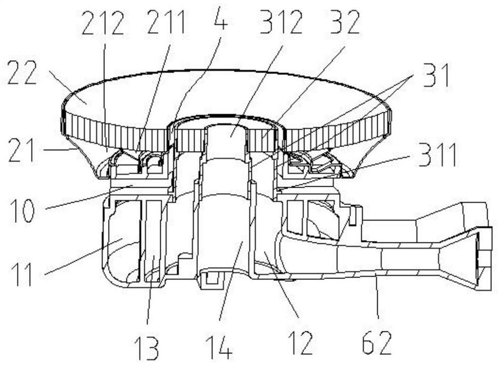
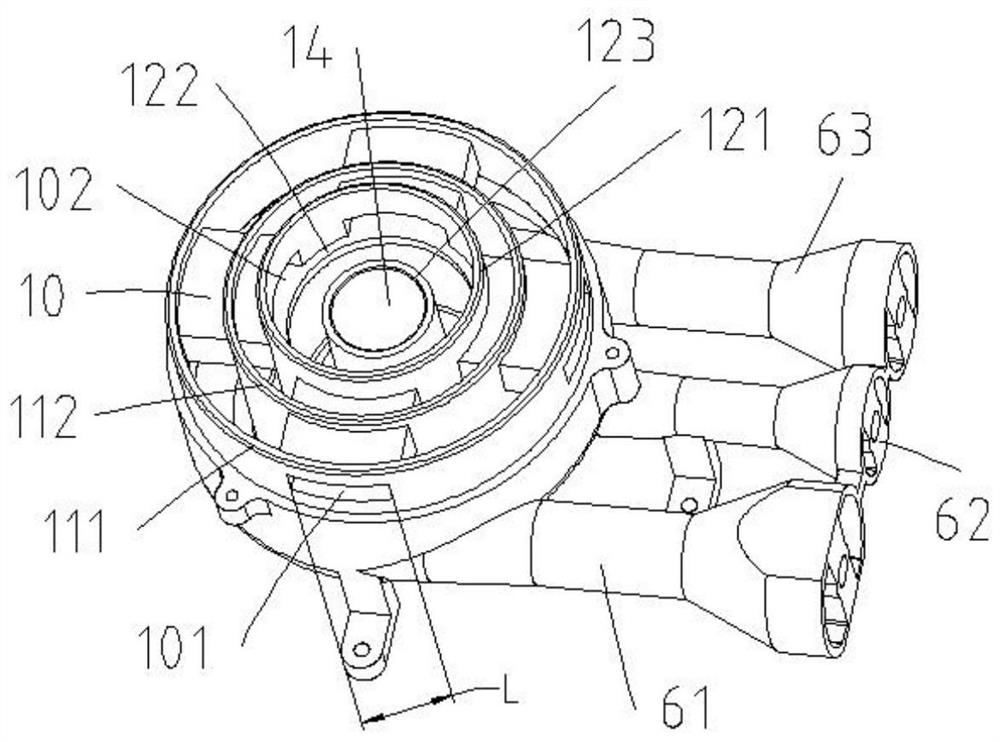
[0027]SeeFigure 1-3 , This embodiment provides an infrared burner, including a furnace head 1, an outer combustion body assembly 2 and an inner combustion body assembly 3, wherein the furnace head 1 is provided with an upwardly opening outer ring air cavity 11 and an inner ring air cavity 12 , The stove head 1 is provided with a number of horizontally arranged air channels 10, the inlet 101 of the air channel 10 is arranged on the upper end of the outer side wall of the stove head 1 and above the cooker panel, and the outlet 102 is located on the inner ring outer wall of the inner ring air cavity 12 121 is connected to the inner ring air cavity 12, so that the secondary air required for the combustion of the infrared burner is provided by the atmosphere on the upper side of the stove panel through the air channel 10 arranged horizontally on the stove head 1, so as to achieve from the outside of the stove The environment replenishes the secondary air, and there is no need to compete for
Embodiment 2
[0046]The difference between this embodiment and the first embodiment is that the infrared burner only has an inner ring fire and an outer ring fire. Specifically, the furnace head 1 omits the outer ring inner wall 112 of the outer ring air cavity 11, so that the outer ring air cavity 11 and the middle ring air cavity 13 are combined to form an outer ring air mixing cavity. Correspondingly, the outer combustion body assembly 2 omits the partition separating the outer gas distribution plate 21 into the inner gas distribution chamber 211 and the outer gas distribution chamber 212, so that the inner gas distribution chamber 211 and the outer gas distribution chamber 212 are combined to form a more A large air cavity connected to the outer ring air mixing cavity. The annular air passage 4 is located between the outer combustion body assembly 2 and the inner combustion body assembly 3, and the secondary air flowing upward from the annular air passage 4 is used to supplement the radial inner
PUM
 Abstract
Description
Claims
Application Information
 - R&D Engineer
- R&D Manager
- IP Professional
- Industry Leading Data Capabilities
- Powerful AI technology
- Patent DNA Extraction
Browse by: Latest US Patents, China's latest patents, Technical Efficacy Thesaurus, Application Domain, Technology Topic.
© 2024 PatSnap. All rights reserved.Legal|Privacy policy|Modern Slavery Act Transparency Statement|Sitemap