Vehicle energy conversion and emission reduction machine

An energy-saving and emission-reducing technology for vehicles, which is applied to machines/engines, adding non-fuel substances to fuel, internal combustion piston engines, etc., can solve problems such as insufficient fuel combustion, low oxygen concentration in the air, and pollute the environment, so as to improve the environment Pollution problems, sufficient combustion, and the effect of reducing fuel consumption

Pending Publication Date: 2020-03-06
重庆泰节由环保科技有限公司
View PDF0 Cites 1 Cited by
  • Summary
  • Abstract
  • Description
  • Claims
  • Application Information

AI Technical Summary

Problems solved by technology

[0005] The present invention intends to provide an energy-saving and emission-reducing device for vehicles to solve the problems of low oxygen concen

Method used


Image

  • Vehicle energy conversion and emission reduction machine

Examples


Example Embodiment

[0027] Example one

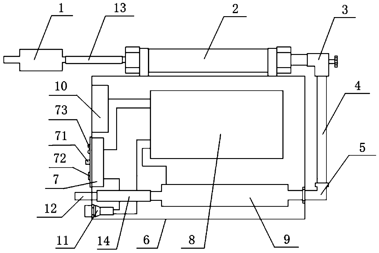
[0028] This example figure 1 Shown:

[0029] An energy-saving emission reduction device for a vehicle includes: a molecular sieve 1, a filter 2, a displacement control loop, a nitrogen and oxygen generating device, and an air outlet 12.

[0030] The intake end of the molecular sieve 1 is connected to the upstream of the air intake system of the automobile engine. The molecular sieve 1 can generate oxygen and increase the oxygen concentration in the air.

[0031] The inlet end of the filter 2 is connected to the outlet end of the molecular sieve 1 through a hose 13, and negative ion materials, such as hydrogen-rich water balls, are added to the filter 2, which can generate oxygen ions and further increase the oxygen concentration in the air.

[0032] The displacement control loop includes a displacement control valve 3, a pipe 4 and an air inlet 5. The displacement control valve 3 is connected to the air outlet of the filter 2, and the pipe 4 is connected between the d


PUM


Abstract

The invention relates to the technical field of vehicle energy conservation and emission reduction, and in particular, discloses a vehicle energy conversion and emission reduction machine. The machinecomprises a molecular sieve for generating oxygen to increase the oxygen concentration in air, a filter connected with the molecular sieve and used for filtering impurities in the air and generatingoxygen ions, a displacement control loop connected with the filter and used for controlling the displacement of the air, a nitrogen and oxygen generation device connected with the displacement controlloop and used for generating nitrogen and oxygen gas, and an exhaust port connected with the nitrogen and oxygen generation device and used for feeding air with high-concentration oxygen into an intake port of a vehicle engine. The molecular sieve capable of generating the oxygen, the filter capable of generating the oxygen ions and the nitrogen and oxygen generation device capable of generatingthe nitrogen and oxygen gas are serially connected into an intake system of a vehicle engine for increasing the concentration of the oxygen in the air by multiple times, so that the combustion of theair and fuels entering the engine is more sufficient, the resource waste is reduced, the oil consumption is reduced, and the environment pollution problem is improved.

Description


Claims


Application Information

Patent Timeline
Owner 重庆泰节由环保科技有限公司
Why Eureka
Try Eureka