Wheel hub motor of rail chassis vehicle
A hub motor and chassis technology, which is applied to the transmission device, electromechanical device, and electrical components driven by an electric motor, can solve the problems of hub motor burnout, heat increase, and hub motor load increase
- Summary
- Abstract
- Description
- Claims
- Application Information
AI Technical Summary
Problems solved by technology
Method used
Image

Examples
Embodiment 1
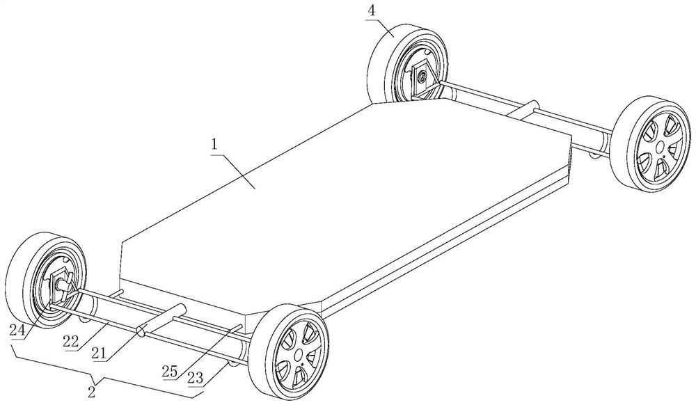
[0032] see figure 1 , a rail chassis wheel hub motor, including a chassis 1 and a vehicle frame 2, the vehicle frame 2 is installed on the front and rear sides of the chassis 1, and the vehicle frame 2 serves as a buffer and support function, and its softness and hardness are adjusted according to the use of the rail chassis vehicle The rigidity makes it more comfortable for the matching device, and the frame 2 also has a certain shock absorption function. The increased shock absorption allows the rail chassis vehicle to have a higher balance effect during operation, and on the frame 2 Connect the suspension 3 for the fixed hub motor, the function of the suspension 3 is to transfer the force and torque between the hub motor assembly 4 and the frame 2, and use the buffer to transmit the uneven road surface to the frame 2 or The impact force of the chassis 1 and reduce the vibration caused by it, the suspension 3 is connected with the hub motor assembly 4 and the cooling device 5,
Embodiment 2
[0043] Change the structure of the cooling device 5, and the remaining parts are the same as the first embodiment. The cooling device 5 includes a sleeve 51, a shaft rod 52, a liquid inlet pipe 53 and a liquid outlet pipe 54, and the liquid inlet pipe 53 and the liquid outlet pipe 54 are symmetrically arranged on the On both sides of the sleeve 51, the liquid inlet pipe 53 and the liquid outlet pipe 54 are located in the radial direction of both sides, and the nozzle diameters of the two are the same. The liquid inlet pipe 53 is connected with the output end of the cooling assembly, and the liquid outlet pipe 54 is connected to the input end of the refrigeration assembly. When the refrigeration assembly is working, the temperature of the cooling liquid is lowered and flows into the liquid inlet pipe 53. What flows in the liquid outlet pipe 54 is the cooling liquid that has exchanged heat and flows into the refrigeration assembly for re-refrigeration. The continuous circulation of
Embodiment 3
[0046] Change the structure of the cooling device 5, and the remaining parts are the same as in Embodiment 1. The cooling device 5 includes a shaft rod 52, a liquid inlet pipe 53 and a liquid outlet pipe 54, and the liquid inlet pipe 53 and the liquid outlet pipe 54 are arranged symmetrically on the sides of the shaft rod 52 respectively. On both sides, and both nozzle diameters are the same, the liquid inlet pipe 53 is connected to the output end of the refrigeration assembly, and the liquid outlet pipe 54 is connected to the input end of the refrigeration assembly, and the temperature of the cooling liquid is reduced when the refrigeration assembly is working. In the liquid pipe 53 and the liquid outlet pipe 54, the cooling liquid that has exchanged heat flows into the refrigeration assembly, and re-refrigerates to complete the continuous circulation of the cooling liquid, thereby realizing the function of continuously cooling the interior of the hub motor assembly 4 , the liqui
PUM
| Property | Measurement | Unit |
|---|---|---|
| Length | aaaaa | aaaaa |
Abstract
Description
Claims
Application Information
 - R&D Engineer
- R&D Manager
- IP Professional
- Industry Leading Data Capabilities
- Powerful AI technology
- Patent DNA Extraction
Browse by: Latest US Patents, China's latest patents, Technical Efficacy Thesaurus, Application Domain, Technology Topic.
© 2024 PatSnap. All rights reserved.Legal|Privacy policy|Modern Slavery Act Transparency Statement|Sitemap