Drill rod supporting piece and supporting system for deep hole machining machine tool

A technology for processing machine tools and supports, applied in the components of boring machines/drilling machines, boring/drilling, metal processing equipment, etc. It can solve the problems of inconsistency of actual processing, no consideration of axial thrust, etc., and reduce straightness. effect of error

Pending Publication Date: 2021-01-15
YANCHENG INST OF TECH
View PDF5 Cites 0 Cited by
  • Summary
  • Abstract
  • Description
  • Claims
  • Application Information

AI Technical Summary

Benefits of technology

This new design allows for precise control over how well an anchor hole or boring tool works when it goes through different types of materials such as concrete without any problems caused by imperfections like uneven surfaces between them. By closely fitting together two supports at one end of each section of the supporting structure, there are no issues where another part affecting its function will also cause errors during use.

Problems solved by technology

This patented describes different types of guns used in industrial applications like tunnels and weapons systems (TWS). These guns require precise alignment while maintaining accurate performance without being influenced by external forces. To address this issue, certain techniques were developed including guiding bushes and intermediates supporting structures called strut keys. Additionally, some advanced technologies involving lasers and other sources of light could impact upon these components, leading to issues related to smooth boreholde drift and reduced quality control over the gun's operation.

Method used


Image

  • Drill rod supporting piece and supporting system for deep hole machining machine tool
  • Drill rod supporting piece and supporting system for deep hole machining machine tool
  • Drill rod supporting piece and supporting system for deep hole machining machine tool

Examples


Embodiment Construction

[0031] The present invention will be described in more detail below with reference to schematic diagrams, wherein preferred embodiments of the present invention are shown, and it should be understood that those skilled in the art can modify the present invention described herein while still achieving the advantageous effects of the present invention. Therefore, the following description should be understood as the broad knowledge of those skilled in the art, but not as a limitation of the present invention.

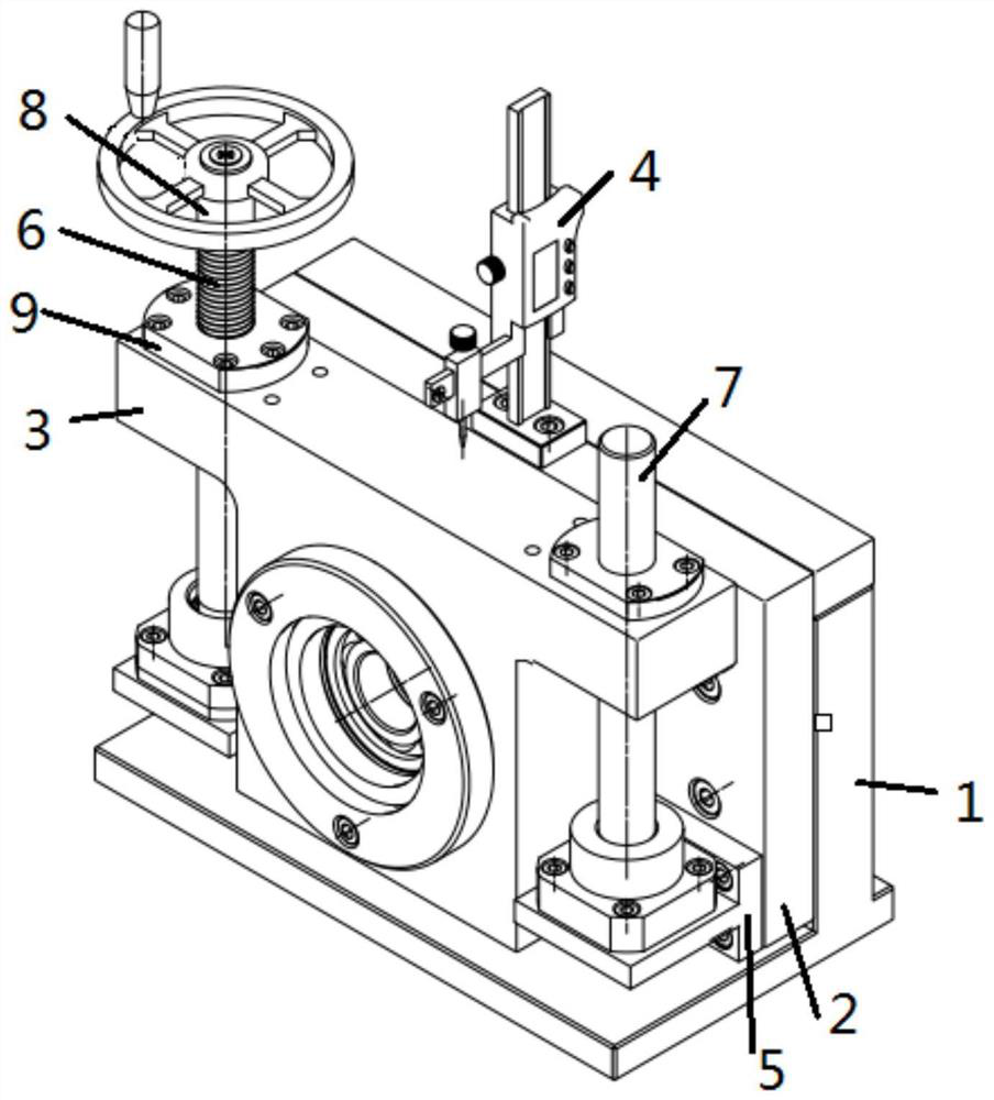
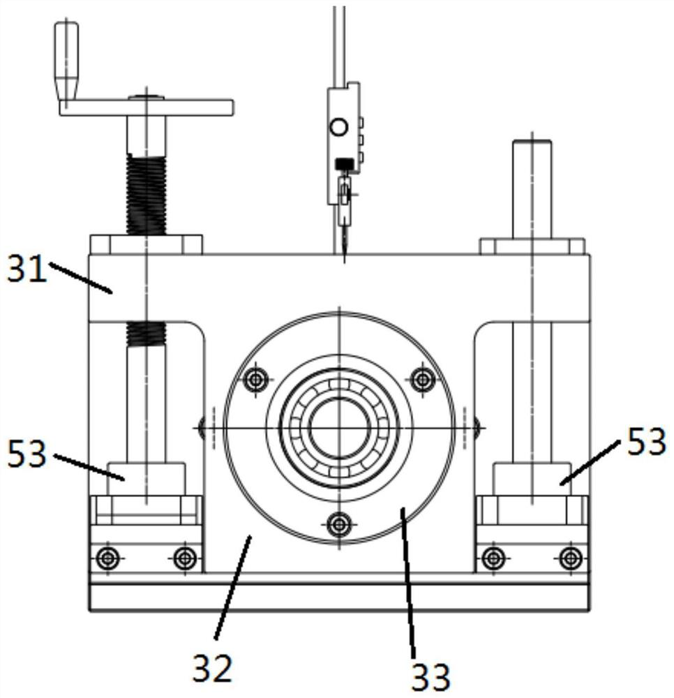
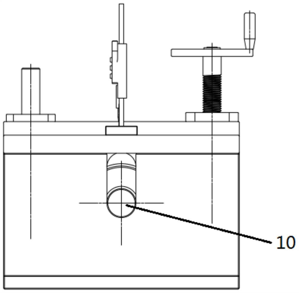
[0032] Such as Figure 1-7 As shown, a drill rod support for a deep hole processing machine tool includes a first support base 1, one side of the first support base 1 is sequentially connected to a support plate 2 and a drill rod support member 3; the first support base 1 1. The support plate 2 and the drill pipe support member 3 are all provided with mounting holes 10 for the drill pipe to pass through; a screw micrometer 4 is fixed on the upper side of the support plate 2;


PUM


Abstract

The invention provides a drill rod supporting piece and supporting system for a deep hole machining machine tool. The drill rod supporting piece comprises a first supporting base for a drill rod to penetrate through, a supporting plate and a drill rod supporting component. A pair of second supporting bases are fixed to the side face, back on to the first supporting base, of the supporting plate, avertically-arranged lead screw is fixed to one second supporting base, and a vertically-arranged guide rod is fixed to the other second supporting base. The upper end of the lead screw and the upperend of the guide rod are both movably installed on the drill rod supporting component. A lead screw nut matched with the lead screw is mounted at the upper end of the lead screw. A bearing used for supporting the drill rod is installed in an installation hole in the drill rod supporting component. The central axis of the drill rod supporting component is higher than the central axis of the drill rod by adjusting the drill rod supporting piece, so that the change of a clearance quantity direction is achieved, and the drill rod supporting component can be used for compensating the influence of other supporting clearance quantities on a straightness error. Therefore, direction adjustment of the supporting clearance quantities is achieved, and the straightness error of a drill bit is reduced.

Description


Claims


Application Information

Patent Timeline
Owner YANCHENG INST OF TECH
Why Eureka
Try Eureka