Equipment fault uploading technology using reactive current pulse signal

A technology of current pulse and equipment failure, applied in the field of communication, can solve problems such as low efficiency and complicated steps for reporting failure information, and achieve the effect of high practicability

Pending Publication Date: 2021-01-22
ZHEJIANG HUAYUN INFORMATION TECH CO LTD
View PDF14 Cites 0 Cited by
  • Summary
  • Abstract
  • Description
  • Claims
  • Application Information

AI Technical Summary

Benefits of technology

The technical effect of this patented method described in the patents relates to improving the accuracy and reliability of detecting electrical failures on electricity distributing systems such as substations or feeders without requiring human intervention during troubleshooting operations. This makes it easier than previous methods that required manually entering data into devices like switches. Additionally, compared to other techniques used for identifying different types of equipment at once, these new approaches are able to identify both high voltage (HV) components and low voltages (LVCs).

Problems solved by technology

This patented describes an improved way that helps manage complex systems by automatically capturing operational data during their failure or trouble shooting period. It uses advanced technologies like machine learning algorithms to identify patterns within these data sources which can help predict future issues with the overall performance of the entire network. By doing things faster than manual inspections, there'll be fewer resource needs compared to traditional methods.

Method used


Image

  • Equipment fault uploading technology using reactive current pulse signal
  • Equipment fault uploading technology using reactive current pulse signal
  • Equipment fault uploading technology using reactive current pulse signal

Examples


Embodiment Construction

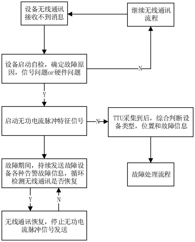
[0027] The technical solutions of the present invention will be further specifically described below through the embodiments and in conjunction with the accompanying drawings. Embodiment: In this embodiment, a technology for sending equipment faults using reactive current pulse signals, such as figure 1 shown, including the following steps:

[0028] (1) There is a problem with the wireless communication of the equipment in the station area, that is, the wireless communication of the equipment cannot receive information.

[0029] (2) The device starts the self-test program, which is used to determine the cause of the failure and determine whether the wireless communication failure of the device is a signal problem or a hardware problem. If the judgment is successful, the device sends a reactive current pulse characteristic signal; if the judgment is not successful in step 2, continue the wireless communication process to check whether the wireless communication of the device can


PUM


Abstract

The invention discloses an equipment fault uploading technology using a reactive current pulse signal. The technology comprises the following steps of when wireless communication of transformer area equipment goes wrong, starting a self-checking program by the equipment, enabling the equipment to send a reactive current pulse characteristic signal, and enabling the distribution transformer monitoring terminal TTU to collect and process reactive current pulse characteristic signals. According to the technical scheme, binary coding is achieved through pulse mode output, reactive current has a basic communication function, a basic function of topology recognition is realized, equipment fault information is sent to a distribution transformer monitoring terminal TTU in time through reactive current pulse characteristic signals, fault uploading is achieved, equipment faults are rapidly processed, and normal operation of a system is ensured.

Description


Claims


Application Information

Patent Timeline
Owner ZHEJIANG HUAYUN INFORMATION TECH CO LTD
Why Eureka
Try Eureka