Anti-pinch and emergency brake quick protection device for injection molding machine

An emergency braking, injection molding machine technology, applied in the direction of emergency protection circuit device, automatic disconnection emergency protection device, electromechanical device, etc. The effect of preventing casualties

Active Publication Date: 2021-02-05
中山市圆美塑料制品有限公司
View PDF10 Cites 0 Cited by
  • Summary
  • Abstract
  • Description
  • Claims
  • Application Information

AI Technical Summary

Problems solved by technology

[0003] The technical problem to be solved by the present invention is to provide an injection molding machine anti-clamping and emergency brake fast protection device, which solves the problem that the injection molding machine cannot prevent the clamping and protect the operator during the manufacturing process

Method used


Image

  • Anti-pinch and emergency brake quick protection device for injection molding machine
  • Anti-pinch and emergency brake quick protection device for injection molding machine
  • Anti-pinch and emergency brake quick protection device for injection molding machine

Examples


Example Embodiment

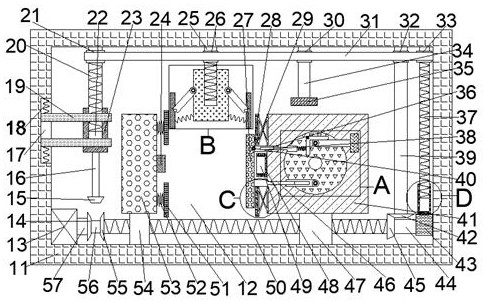
[0017]Combine belowFigure 1-5The present invention will be described in detail, in which, for the convenience of description, the following directions are specified as follows:figure 1 The vertical, horizontal, front and rear directions of the projection relationship are the same.

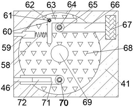
[0018]AttachedFigure 1-5The described device for preventing pinch and emergency braking of an injection molding machine includes an injection molding case 11 in which a processing cavity 12 with a forward opening is provided, and a lower wall of the processing cavity 12 is slidably connected with Positive threaded slider 47, the upper end of the positive threaded slider 47 is fixedly connected with an injection molding host 41, the front end of the injection molding host 41 is rotatably connected with a protruding shaft 69, and the protruding shaft 69 is fixedly connected on the outer peripheral surface There is a disc-shaped wheel 68. Two symmetrical embedded shafts 64 are rotatably connected in the front end


PUM


Abstract

The invention discloses an anti-pinch and emergency brake quick protection device for an injection molding machine. The device comprises an injection molding machine box, a machining cavity with a forward opening is formed in the injection molding machine box, a forward threaded sliding block is connected to the lower wall of the machining cavity in a sliding mode, and an injection molding main machine is fixedly connected to the upper end of the forward threaded sliding block; and a protruding rotating shaft is rotatably connected to the internal of the front end surface of the injection molding main machine. Whether an operator is between injection molding machines or not can be monitored in real time in the using and manufacturing process of the injection molding machines; and if the operator is between the injection molding machines during mold closing of the injection molding machines, emergency braking is immediately carried out to stop mold closing and prevent male and female molds of the injection molding machines from being combined, so that the operator is protected quickly in the operation process and casualties are prevented.

Description


Claims


Application Information

Patent Timeline
Owner 中山市圆美塑料制品有限公司
Why Eureka
Try Eureka