Imaging device and electronic equipment

An imaging device and pixel technology, applied in the field of optical imaging, can solve problems such as difficulty in acquiring multispectral images accurately and efficiently

Active Publication Date: 2021-03-19
OPPO CHONGQING INTELLIGENT TECH CO LTD
View PDF14 Cites 2 Cited by
  • Summary
  • Abstract
  • Description
  • Claims
  • Application Information

AI Technical Summary

Benefits of technology

The invention improves upon existing methods by providing more precise data on how well people work with their technology or what they want it for better performance.

Problems solved by technology

The technical problem addressed in this patented text relates to improving image sharpness by separating light signals from each other based upon their specific colors (red/green) while maintaining high alignment precision during capturing multi-spectrum data.

Method used


Image

  • Imaging device and electronic equipment
  • Imaging device and electronic equipment
  • Imaging device and electronic equipment

Examples


Embodiment Construction

[0023] Example embodiments will now be described more fully with reference to the accompanying drawings. Example embodiments may, however, be embodied in many forms and should not be construed as limited to the examples set forth herein; rather, these embodiments are provided so that this disclosure will be thorough and complete and will fully convey the concept of example embodiments to those skilled in the art. The described features, structures, or characteristics may be combined in any suitable manner in one or more embodiments. In the following description, numerous specific details are provided in order to give a thorough understanding of embodiments of the present disclosure. However, those skilled in the art will appreciate that the technical solutions of the present disclosure may be practiced without one or more of the specific details, or other methods, components, devices, steps, etc. may be adopted. In other instances, well-known technical solutions have not been s


PUM


Abstract

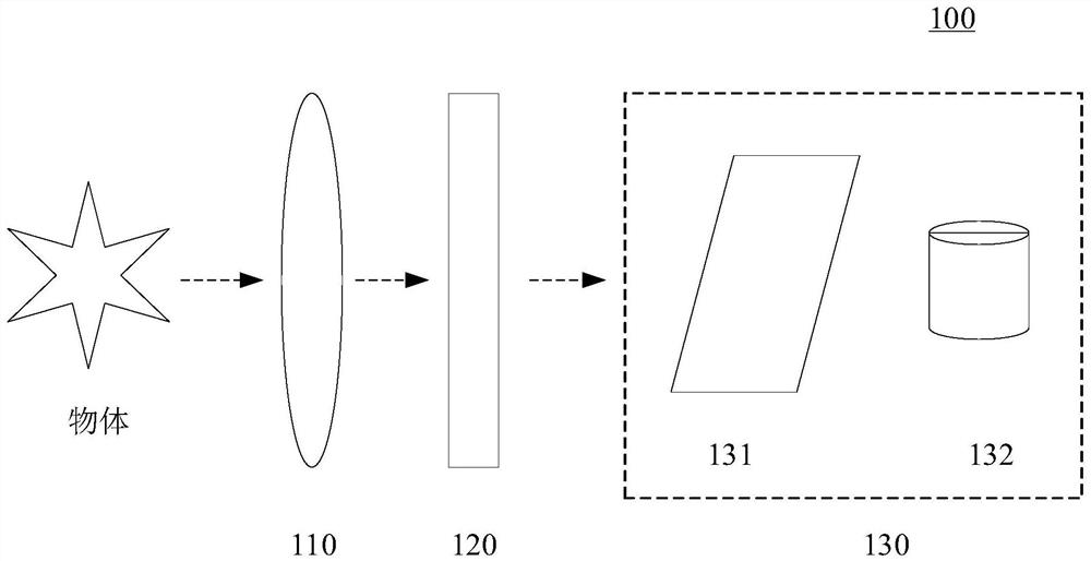
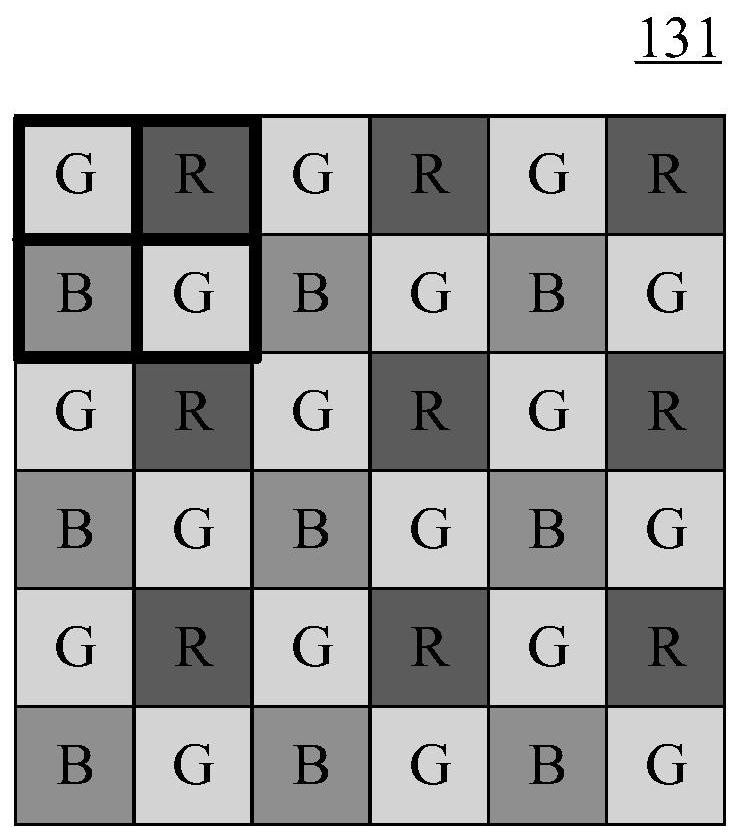
The invention provides an imaging device and electronic equipment, and relates to the technical field of optical imaging. The imaging device comprises an optical splitter and an image detector; an optical splitter which is provided with n main wave bands and used for separating a light beam of one main wave band from the light beam so as to project the light beam to the image detector, wherein n is a positive integer greater than or equal to 2; an image detector which comprises a pixel optical filter and an image sensor; wherein the pixel optical filter is formed by arranging m kinds of pixeloptical filtering units, and m is a positive integer greater than or equal to 2; wherein each pixel filtering unit is provided with n sub-bands, the ith sub-band is located within the ith main band ofthe n main bands, the ith sub-bands of any two pixel filtering units are different, and i is an arbitrary positive integer in [1, n]; the pixel optical filter is used for filtering a light beam of amain waveband into light beams of m sub-wavebands so as to project the light beams to the image sensor; the image sensor is used for outputting m sub-band images corresponding to the m sub-band lightbeams. According to the invention, the multispectral image can be rapidly and effectively acquired.

Description


Claims


Application Information

Patent Timeline
Owner OPPO CHONGQING INTELLIGENT TECH CO LTD
Why Eureka
Try Eureka