Automatic chamfering and shank riveting integrated equipment for nozzle and chamfering and shank riveting process
A nozzle and chamfering technology, applied in the field of chamfering riveting core equipment and chamfering riveting core technology, can solve problems such as unfavorable work, low efficiency, poor precision, etc., and achieve the effects of improving work efficiency, reducing costs, and convenient operation.
- Summary
- Abstract
- Description
- Claims
- Application Information
AI Technical Summary
Benefits of technology
Problems solved by technology
Method used
Image

Examples
Embodiment 1
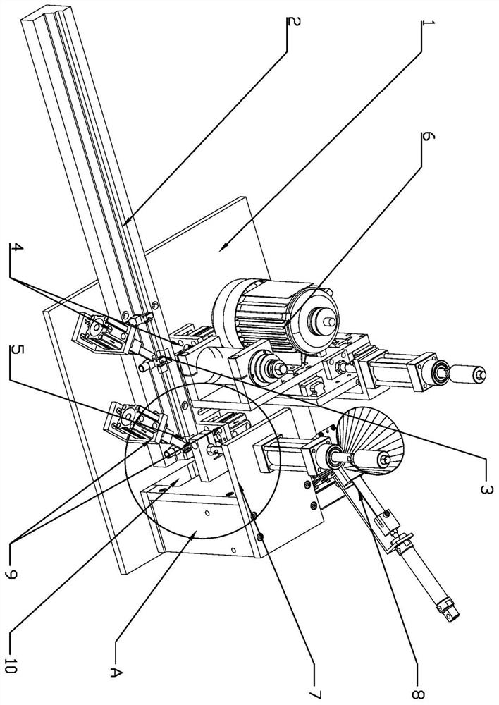
[0038] like Figure 1-8 As shown, in order to achieve the above purpose, the present invention provides an integrated equipment for nozzle automatic chamfering and rivet, including an equipment mounting seat, a placement workbench 1 arranged in conjunction with the equipment installation seat, and a nozzle feeder is arranged on the placement workbench 1 Component 2, several groups of nozzles are placed in sequence on the nozzle feeder component 2; the nozzle chamfering station 3 is set in the middle of the nozzle feeder component 2, and the rivet station is set at the end outlet position of the nozzle feeder component 2 5. The nozzle chamfering station 3 is correspondingly provided with a chamfering assembly 6 and a chamfering clamping assembly 4, and the rivet station 5 is equipped with a riveting part 7, and the riveting part 7 is provided in conjunction with the riveting part 7. The core clamping assembly 9, the riveting part 7 is also equipped with a copper core feeding assem
Embodiment 2
[0041] To achieve the above object, the present invention includes
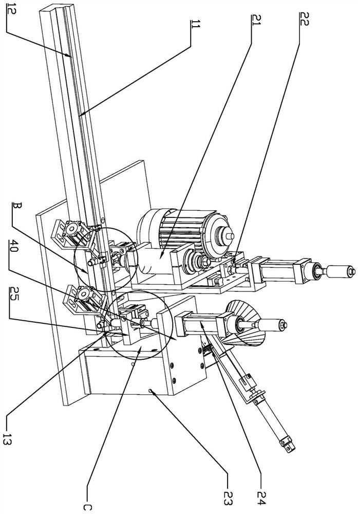
[0042] Step 1: Fill the nozzles in the trough 11 of the nozzle feeder assembly 2 in sequence, the stopper cylinder 16 and the clamping cylinder 19 on the chamfering clamping assembly 4 and the rivet clamping assembly 9 are in a contracted state, chamfering Component 6 and riveting component 7 are in the state to be processed; at the same time, several copper cores are placed in the hopper 32, so that the copper cores can be loaded into the air hole of the nozzle later;
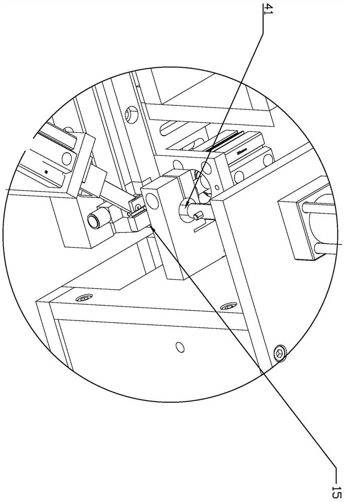
[0043] Step 2: When the nozzle is about to be transported to the middle of the trough 11, the stopper cylinder 16 on the chamfering clamping assembly 4 drives the stopper block 18 to protrude from the chamfering hole 14 and block the nozzle, and the corresponding clamping cylinder 19 Drive the clamping block 20 to perform three-point clamping on the nozzle from an oblique position of 40°-50°;
[0044] Step 3: After clamping, the chamfering movi
PUM
 Abstract
Description
Claims
Application Information
 - R&D Engineer
- R&D Manager
- IP Professional
- Industry Leading Data Capabilities
- Powerful AI technology
- Patent DNA Extraction
Browse by: Latest US Patents, China's latest patents, Technical Efficacy Thesaurus, Application Domain, Technology Topic.
© 2024 PatSnap. All rights reserved.Legal|Privacy policy|Modern Slavery Act Transparency Statement|Sitemap