Machining cutting water filtering device

A water filtration and machining technology, applied in filtration and separation, moving filter element filters, separation methods, etc., can solve the problems of frequent filter cloth replacement, slow cutting fluid filtration, easy clogging, etc. effect, the effect of improving the efficiency of net cleaning

Active Publication Date: 2021-04-23
TIANJIN UNIV OF TECH & EDUCATION TEACHER DEV CENT OF CHINA VOCATIONAL TRAINING & GUIDANCE
View PDF5 Cites 0 Cited by
  • Summary
  • Abstract
  • Description
  • Claims
  • Application Information

AI Technical Summary

Benefits of technology

The technical feature described by this patented technology allows for quicker cleaning while also being able to filter better with its own powered rotating device called Centrifuge.

Problems solved by technology

The technical problem addressed in this patented text relates to reducing excessive amounts of cutting fluids from machines without causing damage due to their high concentration of particulate matter (PM) while still allowing for efficient cleanup after being processed. This issue arises when there may occur sudden changes such as if an abrasively shaped object cuts off too much material before reaching its destination. To address these issues, current methods involve circulating the cutting solution back upstream where it becomes contaminated again until they reach the desired location. However, even with filters made of strong materials like metal wire meshes, frequent replacement poses challenges.

Method used


Image

  • Machining cutting water filtering device
  • Machining cutting water filtering device
  • Machining cutting water filtering device

Examples


Embodiment Construction

[0014] The specific implementation manners of the present invention will be described in further detail below in conjunction with the accompanying drawings.

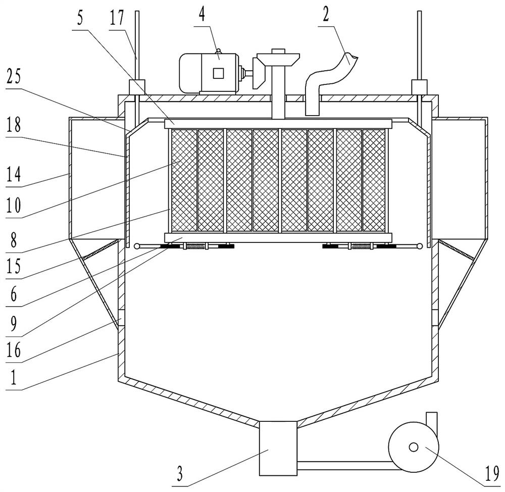
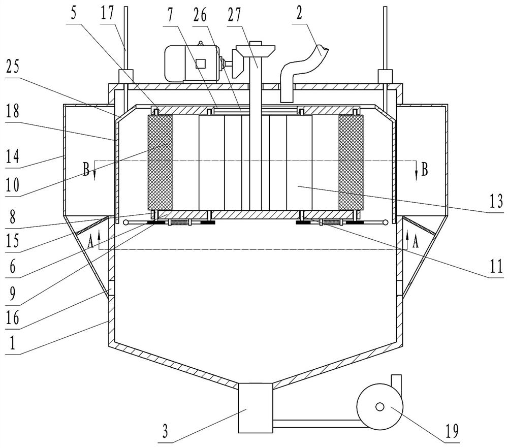
[0015] Depend on Figure 1 to Figure 5 Given, the present invention includes a casing 1, the top of the casing 1 is provided with a water inlet pipe 2, the bottom is provided with a water outlet pipe 3, the inside of the casing 1 is provided with a filter body, and the filter body is driven by a motor 4 to rotate;

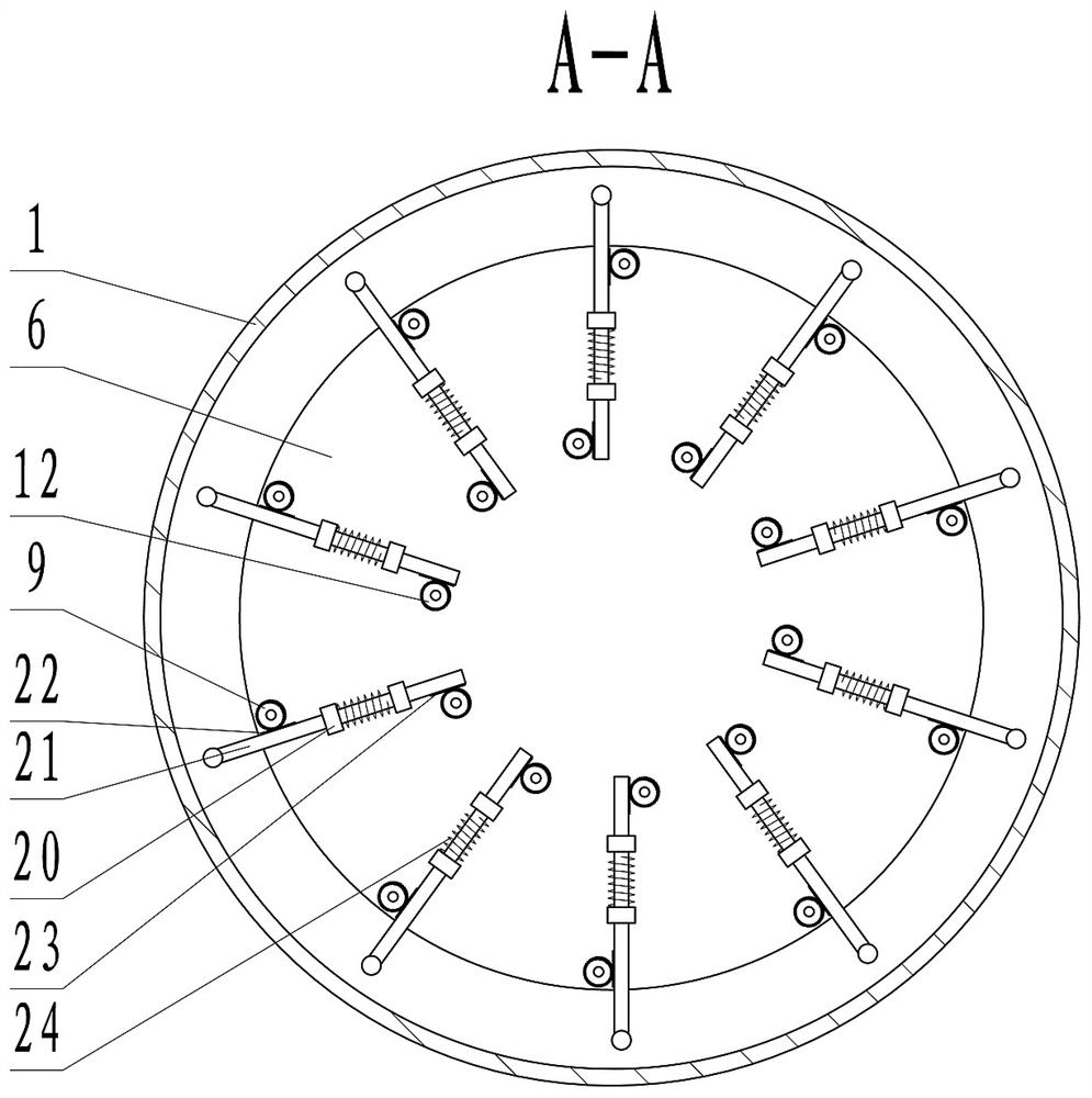
[0016] Described filter body comprises the top board 5 that places horizontally, and the bottom of top board 5 is arranged with bottom plate 6 parallelly; A plurality of first rotating shafts 8 and second rotating shafts 11 are evenly distributed on the circumference, the second rotating shafts 11 are located inside the first rotating shafts 8, and the lower end of the first rotating shafts 8 passes through the bottom plate 6 and is equipped with a first gear 9; each second rotating shaft 8 A vertical filter sc


PUM


Abstract

The invention relates to a machining cutting water filtering device which effectively solves the problems that cutting fluid is low in filtering speed and prone to blockage, and filter cloth is frequently replaced. According to the technical scheme, the device comprises a shell, a water inlet pipe is arranged above the shell, a water outlet pipe is arranged below the shell, a filter body is arranged in the shell and comprises a horizontally-arranged top plate, and a bottom plate is arranged below the top plate in parallel; a water inlet is formed in the middle of the top plate, multiple first rotating shafts and second rotating shafts are circumferentially and evenly distributed between the top plate and the bottom plate, the second rotating shafts are located on the inner sides of the first rotating shafts, and the lower ends of the first rotating shafts penetrate through the bottom plate and are provided with first gears; a vertical filter screen is fixed on each first rotating shaft; the lower end of the second rotating shaft penetrates through the bottom plate and is provided with a second gear; a vertical separation blade is fixed on each second rotating shaft; and the plurality of filter screens and the plurality of separation blades can form a polygonal enclosure in an enclosing manner. Rapid screen cleaning is achieved, and meanwhile the filtering effect and the net cleaning efficiency are improved through centrifugal force.

Description


Claims


Application Information

Patent Timeline
Owner TIANJIN UNIV OF TECH & EDUCATION TEACHER DEV CENT OF CHINA VOCATIONAL TRAINING & GUIDANCE
Why Eureka
Try Eureka